48
IM 01B08B02-01EN
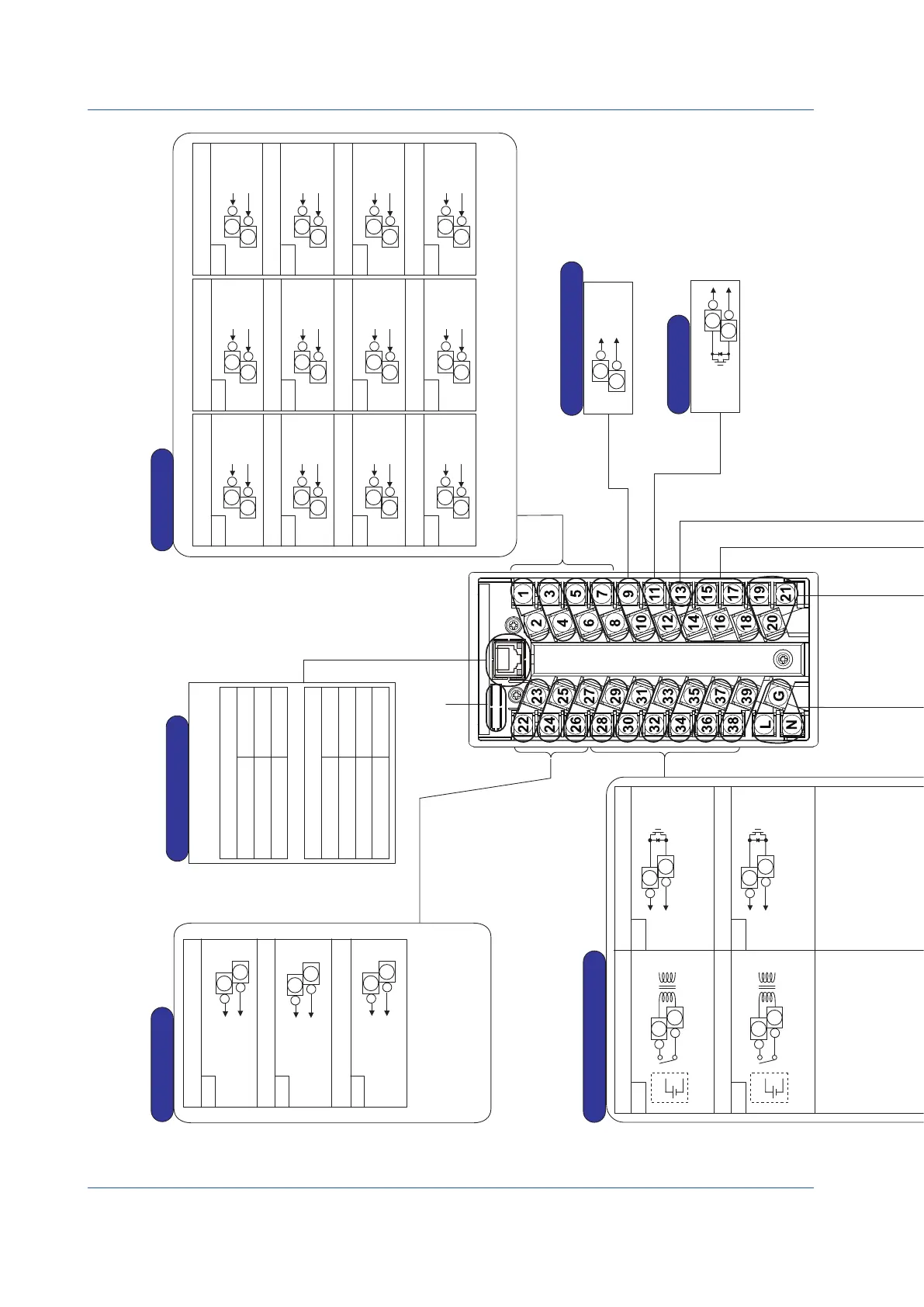
Installation and Wiring
TerminalDiagramsofYS1500/YS1700Single-loop,Cascade,andSelectorModes
Note: Do not use unassigned terminals as relay terminals.
L
G
N
L
N
-
+
Supply voltage (AC)
Supply voltage (DC)
Power Supply
Measurement input
With
voltage
For use as digital input 6
For use as digital input 5
For use as digital input 4
For use as digital input 3
For use as digital input 2
For use as digital input 1
For use as digital output 1
For use as digital output 2
For use as digital output 3
For use as digital output 4
For use as digital output 5
For use as digital output 6
<Factory default> Single loop: High
limit alarm output for PV, Cascade
or selector: loop 1 alarm output
DO1
DI6
X1
Cascade setting input
Output tracking input
Feedforward input
-
Measurement
input 1
+
24 V DC
supply voltage
250Ω
3W
(Optional code /A31) (Optional code /A32)
If feedforward input is not used,
the terminals can be used for
output tracking input.
If cascade setting input 2 is not
used, the terminals can be used
for output tracking input.
Single-loop mode Cascade mode Selector mode
Digital Inputs and Outputs
Analog Outputs
Analog Inputs
Direct Input Signal Output
FAIL Output
Connection of Transmitter Supply Power
To the Expandable
I/O terminal
YS1700-
1
only
(For optional code /A0
)
LCS(+)
LCS(-)
SG
SDA(-)
DCS-LCS Communication
(Optional specifications)
mV input
(/A01)
or
1-5V DC
(/A05)
RTD
input
Potentiometer
input
A
B
B
100%
0%
Frequency
input
Frequency
input
TC
input
Two-wire
transmitter
input
Two-wire
transmitter
input
Two-wire type
(voltage, contact)
Signal
Power
supply
Frequency
input
Power
supply
-
+
Match the wiring resistances of
terminals 19 and 20 with each other.
Match the wiring resistances of
terminals 19 and 21 with each other.
mV input (optional code /A01)
Isolator (optional code /A05)
Potentiometer input
(optional code /A04)
Power feed type,
two-wired
Power feed type,
three-wired
Thermocouple input
(optional code /A02)
RTD input
(optional code /A03)
Two-wire transmitter input
(optional code /A06, /A07)
Two-wire transmitter input
(optional code /A06, /A07)
Frequency input (optional code /A08)
Supply voltage
required
Case of 4 to 20 mA
signal not requiring supply power
Mount the RJC at the terminal
21 side.
Direct Input Terminals
-
+
-
+
The figure at the left shows an example
of the wiring for measurement input 1.
Measurement input 2 can also be
connected in the same way.
► For connecting two transmitters:
see “ Transmitter Supply Power
Wiring” described later.
► For direct input connection:
see “Direct Input Wiring” described later.
If the terminals concerned are used
as digital output, an external power
supply is required.
► For digital output wiring: see
“Wiring for Digital Input/Output
and FAIL Output” described later.
FAIL output requires
external power supply.
► For FAIL output wiring:
see “ Wiring for Digital Input/Output
and FAIL Output” described later.
► For direct input connection: see “Direct Input Wiring”
described later.
<
Factory default>
Used as DO1; it does not function.
+
28
-
29
DI5
<Factory default>
Used as DO2; it does not function.
+
30
-
31
DI4
<Factory default>
Used as DO3; it does not function.
+
32
-
33
DI3
<Factory default>
Used as DO4; it does not function.
+
34
-
35
DI2
<Factory default>
Used as DO5; it does not function.
+
36
-
37
DI1
<Factory default>
No function
+
38
-
39
+
28
-
29
<Factory default> Single loop: Low
limit alarm output for PV, Cascade
or selector: loop 2 alarm output
DO2
+
30
-
31
<Factory default> Single loop: Velocity
alarm output
Cascade: O/C status output
Selector: L/R status output
DO3
+
32
-
33
<Factory default>
C/A, M status output
<Factory default>
C, A/M status output
DO4
+
34
-
35
DO5
+
36
-
37
<Factory default>
Used as DI1; it does not function.
DO6
+
38
-
39
G
10BASE-T/100BASE-TX
RJ45 connector
Number of connection: 2
Ethernet Communication
Color/state
Yellow/Lit
Unlit
Contents
100 Mbps
10 Mbps
Contents
Link
Active
Link fail
Color/state
Green/Lit
Green/Blink
Unlit
Baud rate LED (left side)
Link/Active LED (right side)
Measurement input 1 Measurement input 1
+
Voltage
input
(1-5 V DC)
1
-
2
X2
+
Voltage
input
(1-5 V DC)
3
-
4
X3
+
Voltage
input
(1-5 V DC)
5
-
6
X4
+
Voltage
input
(1-5 V DC)
Voltage
input
(1-5 V DC)
Voltage
input
(1-5 V DC)
Voltage
input
(1-5 V DC)
Voltage
input
(1-5 V DC)
Voltage
input
(1-5 V DC)
Voltage
input
(1-5 V DC)
Voltage
input
(1-5 V DC)
Voltage
input
(1-5 V DC)
Voltage
input
(1-5 V DC)
7
-
8
X1
Cascade setting input
Measurement input 2
Feedforward input
+
1
-
2
X2
+
3
-
4
X3
+
5
-
6
X4
+
7
-
8
X1
Cascade setting input 1
Measurement input 2
Cascade setting input 2
+
1
-
2
X2
+
3
-
4
X3
+
5
-
6
X4
+
7
-
8
+
9
-
10
+
11
-
12
ON in normal
condition
1
2
13
17
18
15
16
17
18
14
SDB(+)
RDA(-)
RDB(+)
+
19
-
20
21
19
20
19
20
+
-
21
19
20
+
-
+
19
-
20
19
21
21
19
20
21
19
20
+
-
21
19
20
0911E.ai
For manipulated output variable 2
and setpoint output, the output
type can be changed using the
analog output-2 selection Y2S and
analog output-3 selection Y3S
engineering parameters.
Digital input hardware specifications:
When voltage is present For no voltage
ON: −0.5 to 1 V DC ON: resistance of 200 Ω or less
OFF: 4.5 to 30 V DC OFF: resistance of 100 kΩ or more
Input contact rating: 5 V DC, 20 mA or more
Digital output hardware specifications:
Rating 30 V DC
200 mA or less (resistive load)
Digital inputs and digital outputs can be selected and used using the DI/DO
specification DIO16 to DIO61 engineering parameters. A function can be set
using DI1F to DI6F and DO1F to DO6F engineering parameters.
RS-485 Communication
Supply voltage 100 to 120 V AC (±10%), 50/60 Hz (±3 Hz) (100 V AC, 24 V DC common power)
(AC): 220 to 240 V AC (±10%), 50/60 Hz (±3 Hz) (220 V AC power)
Supply voltage 24 to 120V DC (±10%) (100 V AC, 24 V DC common power)
(DC): 135 to 190 V DC (±10%) (220 V AC power)
DC power supply can be connected without polarity.
With
voltage
With
voltage
With
voltage
With
voltage
With
voltage
+
22
Y1
Y2
Y3
Manipulated output variable 1
Manipulated output variable 2
Setpoint output
-
23
+
24
-
25
+
26
-
27
Current output
(4-20 mA DC)
Voltage output
(1-5 V DC)
Voltage output
(1-5 V DC)
Figure 9.9

 Loading...


