20
IM 01B08B02-01EN
Monitoring and Control of Regular Operations (Operation Display)
Monitoring and Operating the METER Display
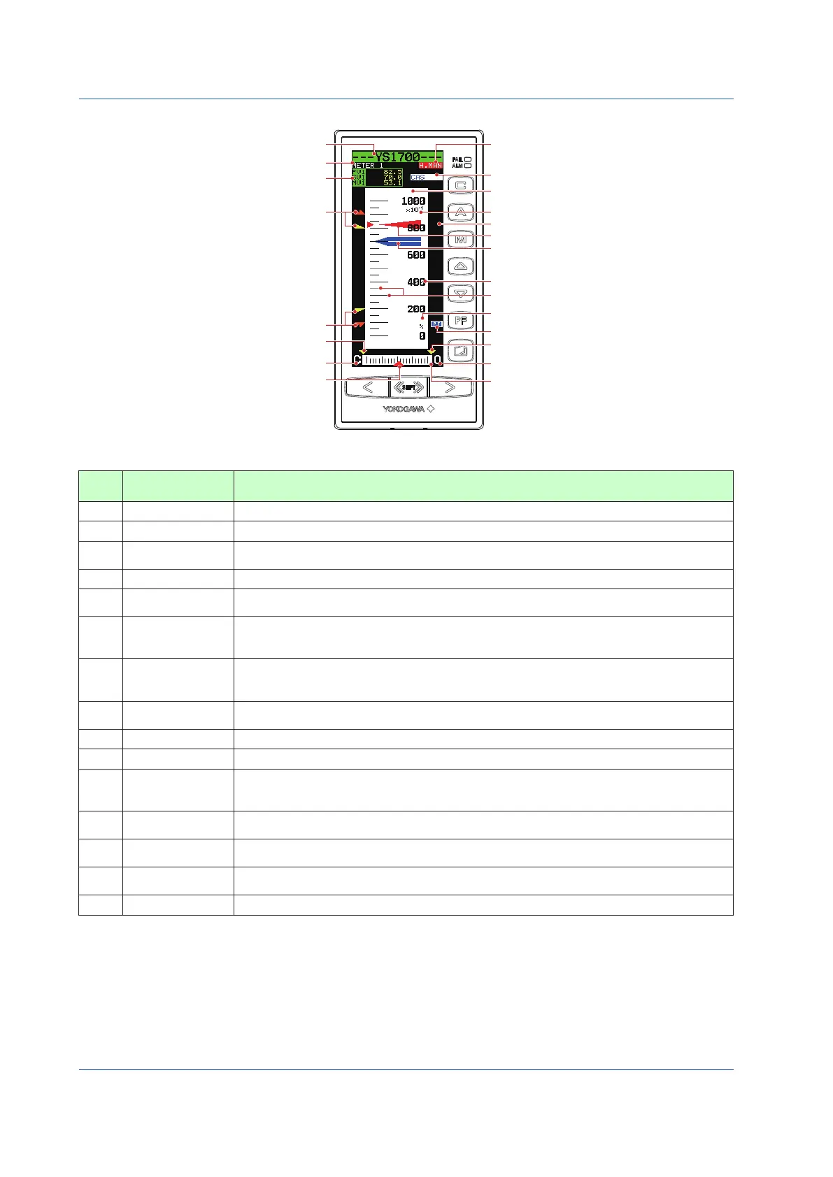
Tag number (1)
Display title (2)
V, SV, MV digital display (3)
HH pointer, PH pointer (11)
LL pointer, PL pointer (11)
ML pointer (14)
MV valve direction (15)
MV pointer (13)
(9) SV pointer
(10) Engineering units
(17) PF key function display
(14) MH pointer
(15) MV valve direction
(12) MV meter scale
(16) Operation status display
(19) Control status display
(4) PV meter scale
(5) Main scale marks, subscale marks
(6) Scale factor
(18) Key LOCK status display
(7) Numerical scale
(8) PV pointer
Figure 5.2
Table 5.6
No. in
Figure
Name Description
(1) Tag number As on the LOOP Display, a tag number appears here.
(2) Display title The title of the display being shown is indicated.
(3)
PV, SV, and MV
digital display
PV, SV, and MV digital values are displayed here.
(4) PV meter scale
The PV meter scale displays main and subscale marks, a numerical scale, a scale factor, and engineering units.
(5)
Main scale marks,
subscale marks
The main scale marks and subscale marks are determined by setting the variables to the 0% value of scale (SCL) and to
the 100% value of scale (SCH), which causes the scale to be automatically divided into divisions based on those values.
(6) Scale factor
The scale range is clearly represented in the range of the number of numerical scale digits using the
power of 10 (× 10
n
). It is possible to set the value of the power, however it can also be automatically
determined from the 0% value of scale (SCL) and 100% value of scale (SCH).
(7) Numerical scale
The numerical scale is automatically determined from the 0% value of scale (SCL) and 100% value of
scale (SCH), and is displayed centered and to the right of the main scale marks. The number of digits to
be displayed is three (or four digits if there is no decimal point).
(8) PV pointer
A PV value is indicated by two pointers (at the left and right sides of the scale). The pointer display
moves up and down with a resolution of 0.5%.
(9) SV pointer
An SV value is indicated with a pointer. The pointer display moves up and down with a resolution of 0.5%.
(10) Engineering units Engineering units (UNIT) are displayed in a maximum of seven digits.
(11)
PH, PL, HH, and LL
pointers
PH values (high limit alarm setpoints for PV) and PL values (low limit alarm setpoints for PV) are indicated
with triangular pointers, while HH values (high-high limit alarm setpoints for PV) and LL values (low-low limit
alarm setpoints for PV) are indicated with pointers which are overlapped pairs of triangles.
(12)
MV meter scale
Scale marks are displayed on the MV meter scale. The mark at the far left is the 0% position and the
mark at the far right is the 100% position. Each scale division is 5%.
(13)
MV pointer
MV values are indicated with a pointer. Since the scale’s full scale is 80 dots (100%), the MV pointer
increases and decreases in a resolution of 1.25%.
(14)
MH and ML pointers
MH values (high limit setpoints of MV) and ML values (low limit setpoints of MV) are indicated with
triangular pointers.
(15)
MV valve direction The MV valve direction is displayed as [C] (closed) or [O] (open). The valve direction can be set.

 Loading...


