21
IM 01B08B02-01EN
Monitoring and Control of
Regular Operations
Monitoring and Control of Regular Operations (Operation Display)
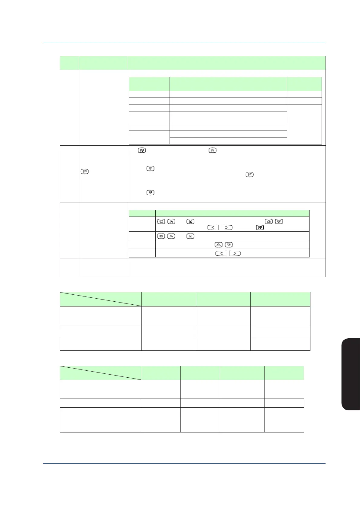
Table 5.7
No. in
Figure
Name Description
(16)
Operation status
display
The controller operation status is displayed.
Display Description
Display
Priority Order
[POWER DOWN] Power down is being detected. (1)
[H.MAN] Hard manual selector switch has been activated. (2)
(No indication) The instrument is operating.
(3)
[STOP] Operation stopped (such as while setting a function
on the Engineering Display, etc.)
[TEST1] Test run mode 1 (only in the programmable mode)
[TEST2]
Test run mode 2 (only in the programmable mode)
Simulation program is being executed
(17)
key function
display
The key function is displayed. The key function display is different in the multi-function
mode and the programmable mode.
1) Multi-function mode
The key function is set using the PF key function selection parameter [PFKEY].
When the STC mode selection is “not OFF” and the “ key has been set to STC”, the
function display becomes [STC]. In other cases, nothing is displayed.
2) Programmable mode
The key function can be defined in user programs.
The function display becomes [PF] in the programmable mode.
(18)
Key LOCK status
display
The key LOCK status is displayed.
Display Description
[ALLK]
, , and keys, SV increase and decrease ( , ) keys, MV
increase and decrease ( , ) keys, and key are disabled.
[MDLK]
, , and keys are disabled.
[SVLK]
SV increase and decrease (
, ) keys are disabled.
[MVLK]
MV increase and decrease (
, ) keys are disabled.
(19)
Control status display
Control status is displayed in abbreviations. Control status display differs according to
the controller mode in the multi-function mode; or according to the control module in the
programmable mode. See Tables 5.8 to 5.10.
Table 5.8 Control Status Display in the YS1500/YS1700 Multi-function Mode
Controller Mode
Display Item
Single Loop Cascade Selector
Control status display (Note 1)
CAS
SPC, DDC
BUA, BUM
CAS
SPC, DDC
BUA, BUM
CAS
SPC, DDC
BUA, BUM
Control substatus display 1 (Note 2)
EXT-MAN,EXT-AUT
EXT-PMV,EXT-TRK
None None
Control substatus display 2 (Note 3)
SV TRK, PV TRK OPEN, CLOSE
SV2-RMT, SV2-LCL
SEL1, SEL2
Table 5.9 Control Status Display in the YS1700 Programmable Mode
Control Module
Display Item
Basic Control
Cascade
Control
Selector Control
Dual-loop
Control
Control status display (Note 1)
CAS
SPC, DDC
BUA, BUM
CAS
SPC, DDC
BUA, BUM
CAS
SPC, DDC
BUA, BUM
CAS
SPC, DDC
BUA, BUM
Control substatus display 1 (Note 2)
None None None None
Control substatus display 2 (Note 3)
None OPEN, CLOSE
SV2-RMT
SV2-LCL
SEL1, SEL2, SEL-
EXT
None
Note 1: Only when the operation mode is in cascade setting automatic control (C mode) is a control status displayed, while nothing is indicated in
automatic control (A mode) or manual control (M mode).
Note 2: When each control substatus is generated, one item is displayed. Nothing is displayed when a status is not generated.
Note 3: One of the control substatuses is always displayed.

 Loading...


