50
IM 01B08B02-01EN
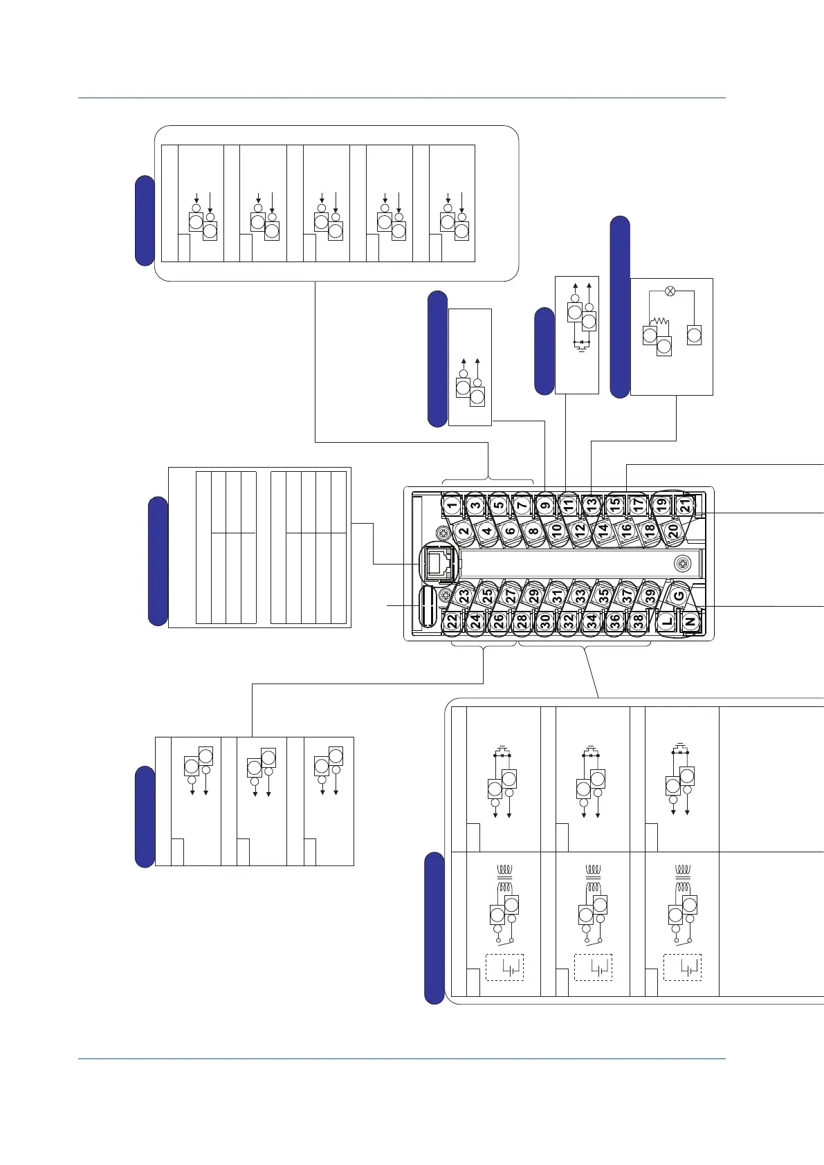
Installation and Wiring
Terminal Diagrams of YS1700 Programmable Mode
Note: Do not use unassigned terminals as relay terminals.
Analog input 1
Analog input 2
Analog input 3
Analog input 4
X1
Analog input 5
If direct input (optional specifications)
is provided, analog input 5 becomes
direct input signal output.
Analog Inputs
+
1
-
2
X2
+
3
-
4
X3
+
5
-
6
X4
+
7
-
8
X5
+
9
-
10
+
Current output
(4-20 mA DC)
22
Y1
Y2
Y3
Analog output 1
Analog output 2
Analog output 3
-
23
+
Voltage output
(1-5 V DC)
24
-
25
+
Voltage output
(1-5 V DC)
or current output
(4-20 mA)
26
-
27
For use as digital input 6
For use as digital input 5
For use as digital input 4
For use as digital input 3
For use as digital input 2
For use as digital input 1
For use as digital output 1
For use as digital output 2
For use as digital output 3
For use as digital output 4
For use as digital output 5
For use as digital output 6
DO1
DI6
+
28
-
29
DI5
+
30
-
31
DI4
+
32
-
33
DI3
+
34
-
35
DI2
+
36
-
37
DI1
+
38
-
39
+
28
-
29
DO2
+
30
-
31
DO3
+
32
-
33
DO4
+
34
-
35
DO5
+
36
-
37
DO6
+
38
-
39
With
voltage
With
voltage
With
voltage
L
G
N
L
N
-
+
Supply voltage (AC)
Supply voltage (DC)
Power Supply
G
Supply voltage 100 to 120 V AC (±10%), 50/60 Hz (±3 Hz) (100 V AC, 24 V DC common power)
(AC): 220 to 240 V AC (±10%), 50/60 Hz (±3 Hz) (220 V AC power)
Supply voltage 24 to 120V DC (±10%) (100 V AC, 24 V DC common power)
(DC): 135 to 190 V DC (±10%) (220 V AC power)
DC power supply can be connected without polarity.
(Optional specifications)
RTD
input
Potentiometer
input
A
B
B
100%
0%
Frequency
input
Frequency
input
Two-wire
transmitter
input
Two-wire
transmitter
input
Two-wire type
(voltage, contact)
Signal
Power
supply
Frequency
input
Power
supply
-
+
Match the wiring resistances of
terminals 19 and 20 with each other.
Match the wiring resistances of
terminals 19 and 21 with each other.
Potentiometer input
(optional code /A04)
Power feed type,
two-wired
Power feed type,
three-wired
Thermocouple input
(optional code /A02)
RTD input
(optional code /A03)
Two-wire transmitter input
(optional code /A06, /A07)
Two-wire transmitter input
(optional code /A06, /A07)
Frequency input (optional code /A08)
Supply voltage
required
Case of 4 to 20 mA
signal not requiring supply power
Direct Input Terminals
-
+
-
+
► For direct input connection: see “Direct Input Wiring”
described later.
+
19
-
20
21
19
20
19
20
+
-
+
19
-
20
19
21
21
19
20
21
19
20
+
-
21
19
20
(Optional code /A31) (Optional code /A32)
LCS(+)
LCS(-)
SG
SDA(-)
DCS-LCS Communication
17
18
15
16
17
18
14
SDB(+)
RDA(-)
RDB(+)
RS-485 Communication
Analog output 3 can be
changed using analog output-3
current/voltage switching
Y3TP engineering parameter.
Factory default: 1-5 V DC
To the expandable
I/O terminal
YS1700-
1
only
If the terminals concerned are used
as digital output, an external power
supply is required.
► For digital output wiring: see
“Wiring for Digital Input/Output
and FAIL Output” described later.
Digital Inputs and Outputs
Digital input hardware specifications:
When voltage is present For no voltage
ON: −0.5 to 1 V DC ON: resistance of 200 Ω or less
OFF: 4.5 to 30 V DC OFF: resistance of 100 kΩ or more
Input contact rating: 5 V DC, 20 mA or more
Digital output hardware specifications:
Rating 30 V DC
200 mA or less (resistive load)
The digital input and output functions can be set using the YSS1000 Setting
Software (sold separately).
With
voltage
With
voltage
With
voltage
Direct Input Signal Output
FAIL Output
(Optional code /A0
)
► For direct input connection:
see “Direct Input Wiring”
described later.
Voltage
input
(1-5 V DC)
+
-
+
11
-
12
ON in normal
condition
9
10
-
Analog
input 1
+
24 V DC
supply voltage
250Ω
3W
Connection of Transmitter Supply Power
The figure at the left shows an
example of the wiring for analog
input 1. Analog inputs 2 to 5
can also be connected in the
same way.
►
For connecting two transmitters:
see “Transmitter Supply Power
Wiring ” described later.
1
2
13
Analog Outputs
FAIL output requires
external power supply.
► For FAIL output wiring:
see “ Wiring for Digital
Input/Output and FAIL Output”
described later.
mV input
(/A01)
or
1-5V DC
(/A05)
mV input (optional code /A01)
Isolator (optional code /A05)
TC
input
Mount the RJC at the terminal
21 side.
21
19
20
+
-
RJC
Voltage
input
(1-5 V DC)
Voltage
input
(1-5 V DC)
Voltage
input
(1-5 V DC)
Voltage
input
(1-5 V DC)
Voltage
input
(1-5 V DC)
10BASE-T/100BASE-TX
RJ45 connector
Number of connection: 2
Ethernet Communication
Color/state
Yellow/Lit
Unlit
Contents
100 Mbps
10 Mbps
Contents
Link
Active
Link fail
Color/state
Green/Lit
Green/Blink
Unlit
Baud rate LED (left side)
Link/Active LED (right side)
Figure 9.10

 Loading...


