63
IM 01B08B02-01EN
Troubleshooting
Troubleshooting
1003E.ai
(5)
(3)
(4)
(1)
(2)
(2)
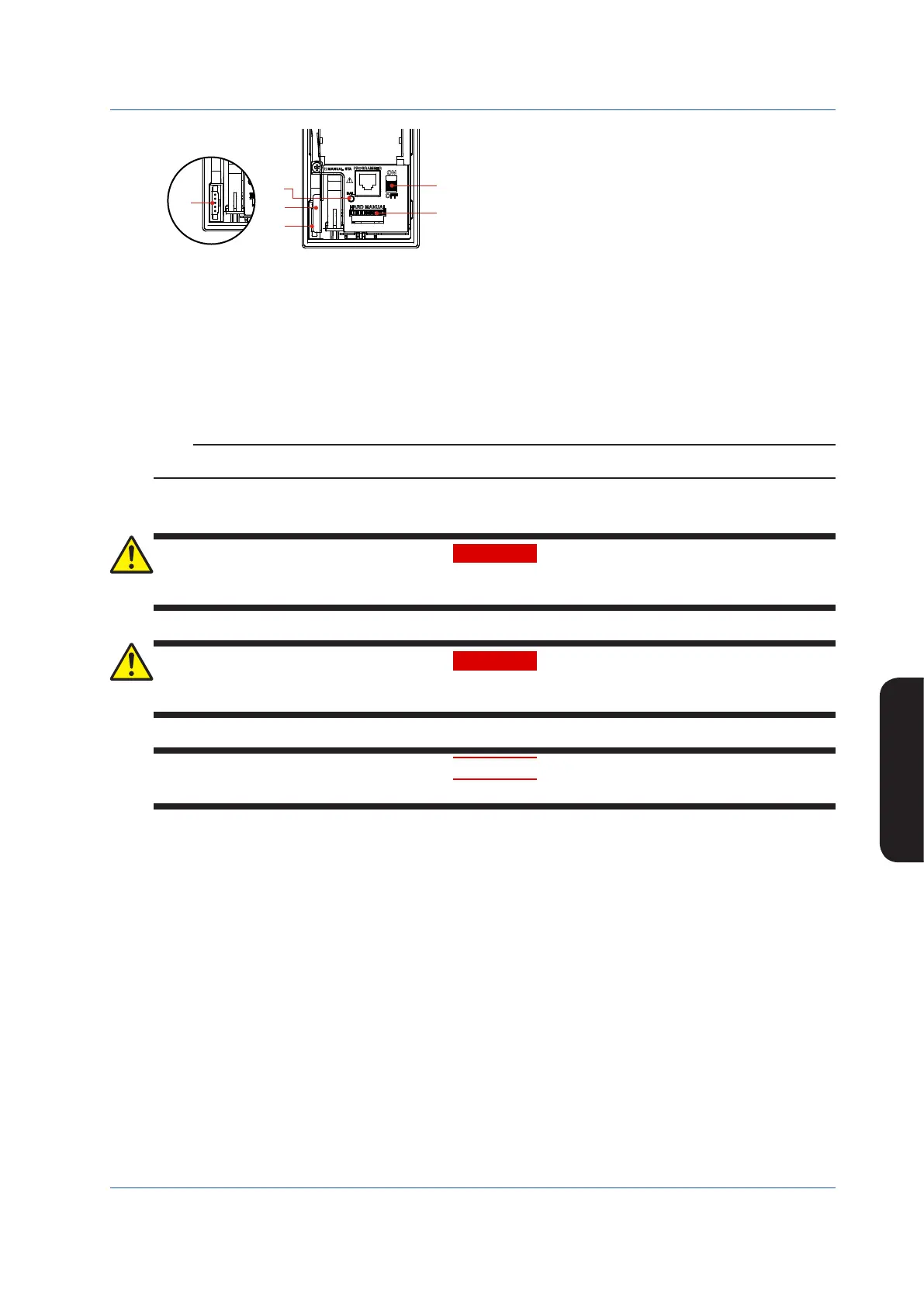
Hard Manual Operation Section
Figure 10.3
Note: Before you connect the cable to the YS110 connector,
touch the metal lever to discharge static electricity.
(1) Metal lever
(2) YS110 standby manual station connection connector
(MANUAL STA)
(3) Hard manual operation wheel (HARD MANUAL)
(4) MV balance lamp (BAL)
(5) Hard manual selector switch (ON/OFF)
• Adjust the value output by the hard manual circuit using the hard manual operation wheel to match it to the Y1 output value (the
control computation circuit’s manipulated output variable) produced immediately before FAIL was displayed. The output value
increases when the operation wheel is turned clockwise, while it decreases when turned counterclockwise.
• When the hard manual circuit output value agrees with the Y1 output value, the MV balance lamp (BAL: green) lights up.
• When the hard manual selector switch is turned ON, the Y1 output value is shifted from the control computation circuit to the
hard manual circuit while the Y1 output value continues to be generated. After that, output operation is available using the hard
manual operation wheel.
Note
The hard manual unit is only available for Y1 output operation.
Online Controller Replacement
WARNING
Do not remove the internal unit from the instrument case. Contact YOKOGAWA’s sales office or sales representative when
replacing the internal unit, as safety standard inspection is required.
WARNING
Explosionhazard.
Do not remove or insert the internal unit or do not connect the YS110 in explosive atmospheres.
CAUTION
Products with optional code /FM or /CSA cannot satisfy the explosion protection standards if the internal unit is removed.
Use of the standby manual station allows the controller to be replaced without interrupting Y1 output in the event of internal unit
failure, etc.
► ForYS110standbymanualstation:seeYS110StandbyManualStationUser’sManual.
Recovery Operations after Power Failures
If a power failure occurs that exceeds the power holdup time, the instrument enters power failure status. Operation after a power
failure differs depending on the power failure time and on the start mode (START) engineering parameters that have been set.
The following action occurs with the factory default values.
► Foroperationafterpowerfailure:seeChapter6,ProcessingduringPowerFailures,intheYS1500IndicatingController/YS1700Programmable
Indicating Controller User’s Manual.
• Momentary power interruption of less than 2 seconds
The instrument continues to operate the same as it had prior to the momentary power interruption.
• Power failure of 2 seconds or more
The operation mode enters Manual, setpoints (SV) and parameters such as PID are maintained in the same condition as they
werepriortothepowerfailure,andthemanipulatedoutputvariablebecomes−6.3%.
If the self-tuning function is used, the PA1, IA1, and DA1 parameter values are initialized to the PB1, TI1, and TD1 values regard-
less of the start mode. This also holds true for the PA2, IA2, and DA2 parameters. Moreover, the parameters are initialized, so
that CR1 and CR2 = 0, RT1 and RT2 = 1.0, LM1 and LM2 = 0, TM1 and TM2 = 0, and GM1 and GM2 = 0.

 Loading...


