54
IM 01B08B02-01EN
Installation and Wiring
Direct Input Wiring (Optional Code /A0
)
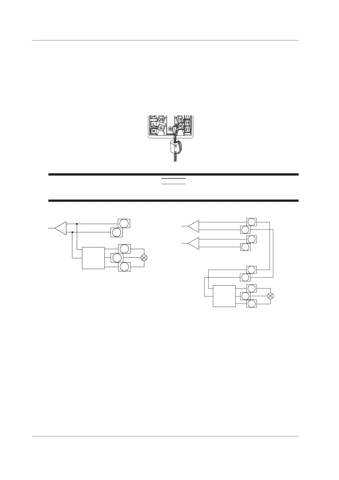
Direct input terminals allow the connection of one of the following: mV voltage, thermocouple, RTD, potentiometer, isolator, two-
wire transmitter, or a pulse signal.
For YS1700, a sensor signal is connected to the direct input terminals, converted into a 1–5 V signal by a signal converter circuit,
andthenreadasanalogdata(X5).Moreover,itisoutputasa1–5VDCsignalfromtheanaloginput5terminals.
For YS1500, a sensor signal is connected to the direct input terminals, converted into a 1–5 V signal by a signal converter circuit,
and then output to the direct input signal output terminals. Connect this signal to the terminals you wish to input to using external
wiring.Connectingittoanaloginput1(X1)allowsyoutomonitormeasuredsignalsusingastandbymanualstationintheeventof
a control and display circuit failure.
A ferrite core is included when the optional code /A0
is specified. Be sure to use the ferrite core when connecting to the wire to
the direct input terminals.
0918-01E.ai
CAUTION
If there is any risk of a surge due to lightning discharge, an arrester should be connected to the direct input signal line.
YOKOGAWA AR series is recommended for the arrester.
X5
9
10
19
20
21
X5 analog
data
Direct input signal
output terminals (*1)
Sensor
*1: If the signal conversion circuit is not used, these
terminals become analog input 5 (X5) terminals.
Signal
conversion
circuit
Figure 9.17
PV1
•
•
•
19
21
20
1
2
9
10
Sensor
Signal
conversion
circuit
External wiring
Direct input signal
output terminal
Figure 9.18

 Loading...


