60
IM 01B08B02-01EN
Troubleshooting
Actions to be Taken in the Event of the FAIL Lamp Lighting Up
If the FAIL lamp lights up, the FAIL Display appears. (If both the main processor (MCU) and display processor (DCU) fail or if the
gate array (GA) is faulty, the FAIL lamp does not light up.)
Table 10.4 List of Causes of Failure
FAIL
Display
Description Processing (Action to be Taken in the Event of Abnormality)
None
Main clock stopped or both the main
processor and display processor are
defective.
Control
computation
stopped
• FAIL contact open
• M lamp lit
• Output HOLD (Y1 to Y4, DO1 to DO10)
• Y1 output can be operated using an MV
operation key (<, SHIFT, >).
• Y1 output can be operated using the hard
manual unit.
• Communication (RS-485, DCS-LCS, or
Ethernet) stopped
SCLK Sub-clock stopped
MCU Main processor (MCU) faulty
DCU Display processor (DCU) faulty
A/D A/D converter faulty
D/A D/A converter faulty
RAM MCU-RAM faulty
ROM MCU-ROM faulty
FRAM FRAM faulty
FLASH Flash memory faulty
OPT Communication/expandable I/O abnormal
SYS System data abnormal
EMPFR FRAM data non-initialized, FRAM data lost
EMPFL Flash data non-initialized, Flash data lost
Displays and Operation in the Event of FAIL
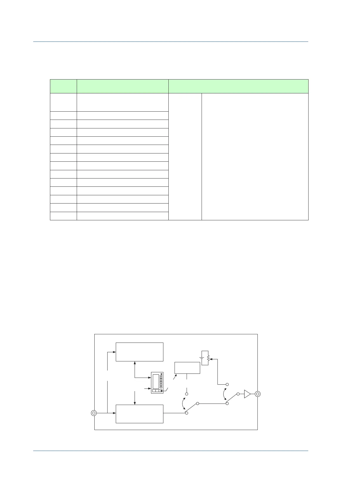
YS1000 has an independent control computation circuit (main processor, MCU), a display operation circuit (display processor,
DCU), and is also equipped with a current output backup circuit.
If the control computation circuit fails, control computation stops, and outputs (Y1 to Y4 and DO1 to DO10) are changed to held
status. The communication function also stops. In this case, the FAIL Display is shown by the display operation circuit. This circuit
measuresanddisplaysanaloginputdata(X1),allowingacurrentoutputsignal(Y1)tobemanipulatedusingMVoperationkeys.
The display cannot be switched.
If the display operation circuit fails, both normal display and operation are disabled, thereby causing control computation to be
stopped and outputs (Y1 to Y4 and DO1 to DO10) to change to held status. The communication function also stops. In this case,
theFAILDisplayisshownbythecontrolcomputationcircuit.Thiscircuitmeasuresanddisplaysanaloginputdata(X1),allowinga
current output signal (Y1) to be manipulated using MV operation keys. The display cannot be switched.
Regardless of the occurrence of a failure, the front panel of the instrument can be swung up to operate a current output signal (Y1)
using the hard manual operation wheel (when the instrument is equipped with the hard manual unit (i.e. with the designation of
suffix code -1
).
Moreover, use of the YS110 standby manual station facilitates the replacement of the controller’s internal unit without interrupting
outputs.
Control computation circuit
(main processor: MCU)
At MCU
failure
Display
control section
At DCU
failure
Hard manual
operation circuit
Abnormal
Normal
OFF
ON
(PV input)
Output
holding circuit
Normal
(MV output)
At DCU failure
MV operation
Display operation circuit
(Display processor:
DCU)
Figure 10.1 Output Backup System

 Loading...


