29
IM 01B08B02-01EN
Monitoring and Control of
Regular Operations
Monitoring and Control of Regular Operations (Operation Display)
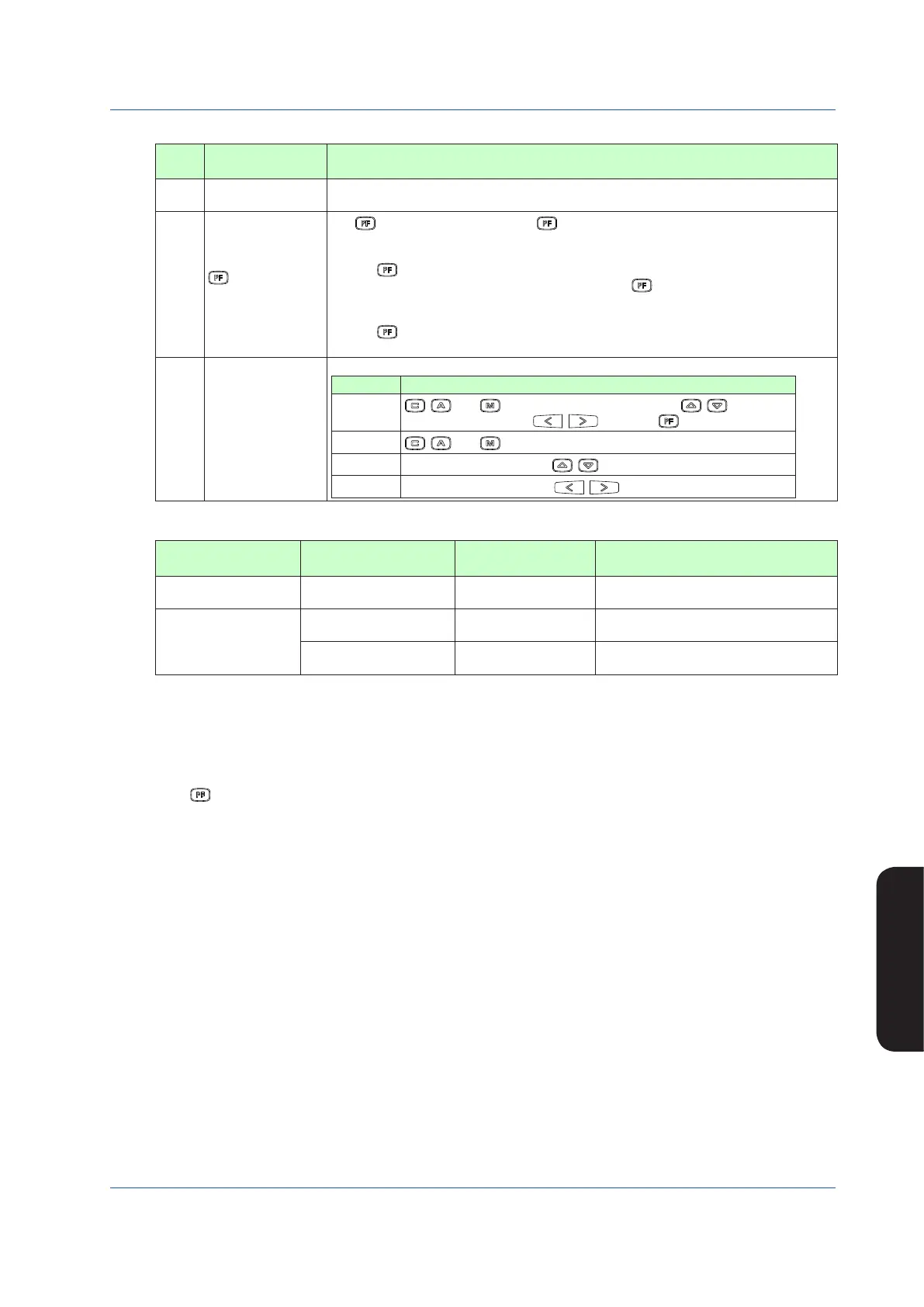
Table 5.16
No. in
Figure
Name Description
(14) MV display
The MV bar, MV scale, MH pointer, ML pointer, MV underflow, MV overflow, and MV valve
direction are displayed. The display contents are the same as those of the LOOP Display.
(15)
key function
display
The key function is displayed. The key function display is different in the multi-function
mode and the programmable mode.
1) Multi-function mode
The key function is set using the PF key function selection parameter [PFKEY].
When the STC mode selection is “not OFF” and the “ key has been set to STC”, the
function display becomes [STC]. In other cases, nothing is displayed.
2) Programmable mode
The key function can be defined in user programs.
The function display becomes [PF] in the programmable mode.
(16)
Key LOCK status
display
The key LOCK status is displayed.
Display Description
[ALLK]
, , and keys, SV increase and decrease ( , ) keys, MV
increase and decrease ( , ) keys, and key are disabled.
[MDLK]
, , and keys are disabled.
[SVLK]
SV increase and decrease (
, ) keys are disabled.
[MVLK]
MV increase and decrease (
, ) keys are disabled.
Table 5.17
Controller Mode or
Control Module
Control Substatus
Display in DUAL Display
Description Control Substatus Display in LOOP
Display
Cascade or CSC control
module
O The cascade is open. OPEN
Selector or SSC control
module
S
The corresponding loop
has been selected.
SEL1 (where “S” is displayed in the loop1) or
SEL2 (where “S” is displayed in the loop2)
E
An external signal has
been selected.
EXT(intheprogrammablemode)
► Controlmodule:YSS1000SettingSoftware/YS1700ProgrammableFunctionUser’sManual
Operating the DUAL Display
The following four operations can be conducted on the DUAL Display:
(1) Operation mode switching operation
(2) SV setting operation
(3) MV operation
(4) key operation
The operation methods are the same as those of the LOOP Display.
When the display title is DUAL1, the loop 1 can be operated; when it is DUAL2, the loop 2 can be operated. To make the operable
loop easy to identify, the color of the backlit tag number, PV bar, and MV bar on the operable loop are displayed in the same color
(selected loop color).

 Loading...


