EasyManua.ls Logo

York D*SC360 User Manual

York D*SC360
25 pages
To Next Page IconTo Next Page
Page #1 background imageLoading...
Page #1 background image
GENERAL
This instruction covers the installation, start-up and operation
of these air conditioning units. If the unit includes a heating
option, use this instruction in conjunction with the proper heat-
ing instruction.
530.25-N1.1 - Gas Heat Option
530.25-N1.9 - Electric Heat Option
These units are completely packaged, factory charged, cooling
only or cooling/heating air conditioners, primarily designed for
rooftop installation.
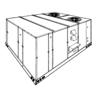
See Figure 1 for the internal arrangement of the unit compo-
nents. These units have semi-hermetic compressors with
blocked suction unloading for efficient full and part load opera-
tion and can be equipped with an economizer option to provide
cooling with outdoor air when the temperatures and the humid-
ity of the outdoor air permit. The unit can also be equipped with
exhaust air fans for use in conjunction with the economizer
option.
All electrical controls are located on one side of the unit and
are readily accessible for maintenance, adjustment and serv-
ice. All wiring (power and control) and piping can be made thru
the bottom or the side of the unit.
Units are available with bottom duct connections for roof
mounted installations or may be field converted for end duct
connections. Refer to Form 530.25-N1.5.
The following safety precautions apply to gas-fired units:
INSPECTION
As soon as a unit is received, it should be inspected for possible
damage during transit. If damage is evident, the extent of the
damage should be noted on the carrier’s freight bill. A separate
request for inspection by the carrier’s agent should be made in
writing. Refer to Form 50.15-NM for additional information.
REFERENCE
Additional information on the design, installation, operation and
service of this equipment is available in the following reference
forms:
55.70-N1 - General Installation
55.70-N2 - Pre-start & Post-start Check List
Renewal Parts:
Refer to the Renewal Parts Manual for complete listing of
replacement parts on this equipment.
All forms referenced in this instruction may be ordered from:
Publications Distribution Center
Unitary Products Group
P.O. Box 1592, York, Pa. 17405
®
SUNLINE SERIES
SINGLE PACKAGE AIR CONDITIONERS
INSTALLATION INSTRUCTION
Supersedes: Nothing
530.25-N3Y (394)
MODELS D*SC360 & 480
035-11820
CAUTION
THE ENCLOSED INSTALLATION INSTRUCTIONS AND ANY APPLICABLE
LOCAL, STATE, AND NATIONAL CODES INCLUDING, BUT NOT LIMITED
TO, BUILDING, ELECTRICAL, AND MECHANICAL CODES.
THIS PRODUCT MUST BE INSTALLED IN STRICT COMPLIANCE WITH
WARNING
OPERATION OF THE PRODUCT COULD CAUSE PERSONAL INJURY
OR PROPERTY DAMAGE.
INCORRECT INSTALLATION MAY CREATE A CONDITION WHERE THE
Installer should pay particular attention to the words:
NOTE, CAUTION
and
WARNING
. Notes are intended to clarify or make
the installation easier.
Cautions are given to prevent equipment damage. Warnings are given to alert installer that personal injury
and/or equipment damage may result if installation procedure is not handled properly.
FOR YOUR SAFETY
Do not store or use gasoline or other flammable
vapors and liquids in the vicinity of this or any
FOR YOUR SAFETY
If you smell gas:
1. Open windows.
2. Don’t touch electrical switches
3. Extinguish any open flame.
208/230/460
VOLT ONLY
208/230/575
VOLT ONLY

Table of Contents

Question and Answer IconNeed help?

Do you have a question about the York D*SC360 and is the answer not in the manual?

York D*SC360 Specifications

General IconGeneral
BrandYork
ModelD*SC360
CategoryAir Conditioner
LanguageEnglish

Summary

General Information and Inspection

General

Covers installation, start-up, and operation of air conditioning units, including heating options.

Inspection

Procedure for inspecting the unit for damage during transit and documenting any issues.

References

Lists additional forms for design, installation, operation, and service of the equipment.

Installation Procedures

Limitations and Clearances

Specifies installation codes, standards, and required clearances for proper unit operation.

Rigging and Mounting

Details proper lifting techniques and structural requirements for unit installation, including roof curbs.

Electrical and Drain Connections

Condensate Drain Connection

Instructions for connecting the condensate drain, emphasizing trap requirements for water seal.

Power and Control Wiring

Guidance on electrical wiring installation, grounding, and conduit entry points for unit power and control circuits.

Control Wiring Routing

DSC360 Control Wiring Entry

Routing instructions for control wiring into the DSC360 model unit via bottom or side entry.

DSC480 Control Wiring Entry

Routing instructions for control wiring into the DSC480 model unit via bottom or side entry.

Control Wiring Diagram (No Status Panel)

Wiring Without Status Panel

Diagram illustrating control wiring connections for units without a status panel, showing thermostat and PCB connections.

Control Wiring Diagram (With Status Panel)

Wiring With Status Panel

Diagram illustrating control wiring connections for units with a status panel, including thermostat and PCB connections.

Control Wiring Diagrams (Solid State)

Solid State Control Wiring

Diagrams for control wiring with solid state control, covering units with and without status panels.

Electrical Data Tables

Data Without Exhaust Air Fans

Table detailing electrical specifications for units without exhaust air fans, including compressors and motors.

Data With Exhaust Air Fans

Table detailing electrical specifications for units with exhaust air fans, including motors.

Unit Dimensions and Clearances

Minimum Clearances

Table listing minimum required clearances for various unit sections and orientations for installation.

Unit Dimensions Table

Table of dimensional data for DSC360 and DSC480 models, including opening sizes.

Duct Connections and Filters

Duct Connections

Guidance on connecting supply and return air ducts to the unit and roof curb package.

Filters

Information on filter types, sizes, and quantities required for optimal unit air filtration.

Operation - Economizer System

Economizer Rain Hood Option

Details the economizer option, including factory-mounted components and rain hood assembly.

Fixed Outside Air & Exhaust Options

Covers fixed outside air dampers and exhaust air options with their respective rain hoods.

Operation - Cooling and Exhaust Systems

Cooling System Operation

Explains the normal sequence of operation for the cooling system, including stages and compressor functions.

Exhaust Air System

Details the operation and adjustment procedures for the unit's exhaust air fans.

Operation - Solid State Controls

Solid State Control Logic

Describes the logic panel controlling economizer and cooling stages based on sensor inputs.

Economizer System Operation

Explains economizer system operation, including damper control and low limit functions.

Damper Linkage Adjustment

Provides steps to adjust the linkage between damper motor and blades for proper operation.

Supply Air Blower Adjustment

Blower Adjustment Procedure

Details how to determine and set blower RPM based on CFM and static resistance requirements.

Supply Air Blower Performance

Explains how to use performance data to determine correct blower settings for optimal airflow.

Airflow Measurement and Circuit Board

Supply Air CFM Check

Procedure for measuring supply air CFM using static pressure readings from evaporator coil.

Master Printed Circuit Board

Description of the circuit board, relays, and troubleshooting using a service analyzer.

Service Analyzer and Adjustments

Service Analyzer Operation

How to connect and use the service analyzer for system control override and diagnostics.

Fixed Outside Air Adjustment

Procedure for adjusting the amount of fixed outside air based on return duct static.

Exhaust Air Performance

Chart for determining exhaust air fan performance based on return duct static pressure.

Blower Motor Data and Unit Resistances

Blower Motor and Drive Data

Table detailing blower motor HP, RPM, pulley sizes, and belt specifications.

Unit Resistances

Table of static pressure resistances for various unit options and accessories.

Start-Up Procedures and Safety Features

Crankcase Heaters

Importance of energizing crankcase heaters before compressor start-up to prevent damage.

Safety and Service Features

Overview of safety controls, protections, and features like low/high pressure cutouts and freezestats.

Pre-Start Checks and Maintenance

Pre-Start Check List

A checklist of essential tasks to complete before unit start-up for proper operation.

Maintenance Procedures

Guidance on filter replacement, coil cleaning, drain pan inspection, lubrication, and belt care.
Related product manuals