EasyManua.ls Logo

York D1CG300 - User Manual

York D1CG300
24 pages
To Next Page IconTo Next Page
Loading...
GENERAL
YORK Model DCE and DCG units are single package air
conditioners designed for outdoor installation on a rooftop or a
slab and is manufactured under ISO 9002 Quality System
Certification. The DCE models are cooling only and can be
equipped with factory installed electric heaters for cooling /
heating applications. The DCG models are gas-fired central
heating furnaces with cooling.
The units are completely assembled on rigid, permanently
attached base rails. All piping, refrigerant charge, and electrical
wiring is factory installed and tested. All units require electric
power, duct connections and fixed outdoor air intake damper
(units without economizer or motorized damper option only) at
the point of installation.
The DCG units additionally require gas connection, installation
of the combustion air inlet hood and the flue gas outlet hoods
at the point of installation. The gas-fired heaters have
aluminized-steel tubular heat exchangers and spark ignition
with proven pilot.
Supplemental electric heaters for DCE units have
nickel-chrome elements and utilize single point power
connections.
The following safety precautions apply to DCG units:
INSPECTION
As soon as a unit is received, it should be inspected for possible
damage during transit. If damage is evident, the extent of the
damage should be noted on the carriers freight bill. A separate
request for inspection by the carrier’s agent should be made in
writing. Refer to Form 50.15-NM for additional information.
REFERENCE
Additional information on the design, installation, operation and
service of this equipment is available in the following reference
forms:
55.70-N1 - General Installation
55.70-N2 - Pre-start & Post-start Check List
44-320-10 - Barometric Relief Damper Accessory
530.18-N6.1V - Propane Conversion Accessory
530.18-N6.2V - High Altitude Accessory (Nat. Gas)
530.18-N6.3V - High Altitude Accessory (Propane)
Renewal Parts:
Refer to the Renewal Parts Manual for complete listing of
replacement parts on this equipment.
All forms referenced in this instruction may be ordered from:
Publications Distribution Center
Unitary Products Group
P.O. Box 1592, York, Pa. 17405
APPROVALS
Design certified by ETL & CGA as follows:
1. For use as a central cooling only unit with or without
supplemental electric heat. (DCE models)
2. For use as a forced air furnace with cooling unit. (DCG
models)
3. For use with natural gas or propane gas. (DCG models)
4. For outdoor installation only.
5. For installation on combustible material.
®
SUNLINE 2000
ELECTRIC / ELECTRIC & GAS / ELECTRIC
SINGLE PACKAGE AIR CONDITIONERS
(Constant Air Volume)
INSTALLATION INSTRUCTION
Supersedes: 530.18-N11Y (793) 530.18-N11Y (195)
MODELS D1CE & D1CG300
(8.5 EER)
035-12550
DCG MODEL
SHOWN
208/230/460
VOLT ONLY
Installer should pay particular attention to the words:
NOTE, CAUTION
and
WARNING
. Notes are intended to clarify or make
the installation easier.
Cautions are given to prevent equipment damage. Warnings are given to alert installer that personal injury
and/or equipment damage may result if installation procedure is not handled properly.
208/230/575
VOLT ONLY
FOR YOUR SAFETY
Do not store or use gasoline or other flammable
vapors and liquids in the vicinity of this or any
other appliance.
FOR YOUR SAFETY
If you smell gas:
1. Open windows.
2. Don’t touch electrical switches
3. Extinguish any open flame.
4. Immediately call your gas supplier.
CAUTION
THIS PRODUCT MUST BE INSTALLED IN STRICT COMPLIANCE
WITH THE ENCLOSED INSTALLATION INSTRUCTIONS AND ANY
APPLICABLE LOCAL, STATE, AND NATIONAL CODES
INCLUDING, BUT NOT LIMITED TO, BUILDING, ELECTRICAL,
AND MECHANICAL CODES.
WARNING
INCORRECT INSTALLATION MAY CREATE A CONDITION
WHERE THE OPERATION OF THE PRODUCT COULD CAUSE
PERSONAL INJURY OR PROPERTY DAMAGE

Table of Contents

Question and Answer IconNeed help?

Do you have a question about the York D1CG300 and is the answer not in the manual?

York D1CG300 Specifications

General IconGeneral
BrandYork
ModelD1CG300
CategoryAir Conditioner
LanguageEnglish

Summary

GENERAL INSTALLATION GUIDELINES

Safety Precautions

Key safety measures for handling and operating the unit, particularly concerning gas.

Transit and Initial Inspection

Procedures for inspecting the unit for damage upon receipt and reporting any issues.

Reference Documentation

List of available forms for detailed information on installation, operation, and service.

Approvals and Certifications

Details on ETL and CGA design certifications for the unit's intended use.

Important Cautions

Notes regarding strict compliance with installation instructions and codes to prevent damage.

Critical Installation Warnings

Alerts about potential personal injury or property damage from incorrect installation.

INSTALLATION REQUIREMENTS

Applicable Codes and Limitations

National and local safety codes that must be followed during installation.

Site Selection and Location

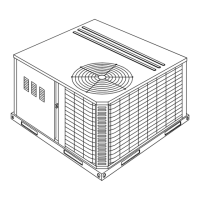
Guidelines for choosing an appropriate installation site, considering airflow and exposure.

Rigging, Handling, and Lifting

Safe procedures for moving and lifting the unit, including equipment and techniques.

Required Clearances

Specifications for maintaining adequate space around the unit for operation and service.

DUCTWORK AND UNIT COMPONENTS

Ductwork Design Standards

Recommendations for designing supply and return air duct systems based on ACCA standards.

Fixed Outdoor Air Intake Damper Installation

Instructions for installing the pre-assembled damper baffle for outdoor air intake.

Condensate Drain Plumbing

Requirements for connecting the condensate drain line in compliance with local codes.

Compressor and Filter Access

Information on compressor mounting and filter installation and maintenance.

Service Access Panels

Locations of removable panels providing access to internal components for service.

CONTROL AND POWER WIRING

Thermostat Wiring Configurations

Diagrams for connecting various thermostat types for cooling and heating operations.

Power Wiring Connections

Guidance for connecting the main power supply to the unit's control box.

Control Wire Gauge Selection

Table specifying wire sizes and maximum lengths for control wiring based on current.

ELECTRICAL AND GAS CONNECTIONS

Thermostat Installation Guidelines

Recommendations for optimal thermostat placement and wiring connections.

Field Wiring Standards

Conformity requirements for field wiring to National Electrical Code and Canadian Electrical Code.

Optional Electric Heater Wiring

Instructions for wiring optional electric heaters for DCE models.

Combustion Air and Venting

Details on discharging combustion products and installing vent hoods for DCG models.

Gas Piping and Connection

Guidance on sizing, routing, and connecting gas supply lines for DCG units.

PROPANE GAS SPECIFICS

LP Unit Conversion and Piping

Information on converting units for L.P./propane gas and related piping requirements.

UNIT ACCESSORIES AND OPTIONS

Vent and Combustion Air Hoods

Instructions for installing vent and combustion air hoods for DCG models.

Economizer Damper Rain Hood

Guidance for field assembly and installation of an economizer/motorized damper rain hood.

Enthalpy Set Point Adjustment

Procedure for setting the enthalpy set point and checking damper movement.

Power Exhaust;Barometric Relief Option

Details on the installation of power exhaust/barometric relief damper and rain hood.

SYSTEM OPERATION MODES

Cooling System Overview

Description of the factory-charged air-cooled condenser cooling section.

Preliminary Cooling Start-up

Procedure for energizing crankcase heaters and initial compressor start-up.

Cooling Sequence (No Outdoor Air)

Operation sequence for cooling when no outdoor air options are selected.

Economizer Cooling Sequence (Single Sensor)

Operation sequence for cooling with a single enthalpy sensor and economizer.

Economizer Cooling Sequence (Dual Sensor)

Operation sequence for cooling with dual enthalpy sensors and economizer.

Economizer with Power Exhaust

Combined operation of economizer and power exhaust systems.

Motorized Outdoor Air Dampers

Operation sequence for units with motorized outdoor air dampers.

Continuous Blower Operation

Method for enabling continuous blower operation via thermostat setting.

Refrigerant Safety Controls

Description of safety controls like suction line freezestat and high pressure cutout.

Electric Heating Sequence

Sequence of operation for electric heating based on thermostat settings.

GAS HEATING OPERATION AND SAFETY

Heat Anticipator Setpoints

Guidelines for setting heat anticipators to ensure correct heating cycle length.

Gas Heating Sequence

Step-by-step description of how the gas heating section operates.

Gas Heating Safety Controls

Overview of safety controls specific to the gas heating system, including limit controls and redundant valves.

START-UP AND GAS ADJUSTMENTS

Heat Anticipator Setting Table

Table providing AMP settings for TH1 and TH2 based on heater KW and voltage.

Pre-Start Inspection Checklist

Essential checks to perform before initial unit start-up, including gas type and hood installation.

Pilot and Burner Ignition

Instructions for initiating pilot and main burner ignition sequence.

Manifold Gas Pressure Adjustment

Procedure for adjusting the automatic gas valve to set manifold gas pressure.

BURNER AND BLOWER CHECKS

Pilot Flame Checkout

Procedure for checking and adjusting the pilot flame for proper sensor coverage.

Supply Air CFM Measurement

Methods for checking and adjusting supply air CFM using blower performance data.

Burner Service Instructions

Steps for accessing and servicing burners, pilots, and orifices.

Burner Air Shutter Adjustment

Procedure for adjusting air shutters to achieve a blue flame appearance.

PERFORMANCE TESTING AND ADJUSTMENT

Evaporator Coil Pressure Drop

Method for measuring pressure drop across the evaporator coil to determine CFM.

Temperature Rise Adjustment

Procedure for adjusting blower CFM to achieve the specified temperature rise.

Belt Drive Blower Adjustment

Instructions for adjusting belt tension and pulley settings for optimal blower performance.

Natural Gas Input Check

Procedure for measuring and verifying natural gas input rate using the gas meter.

ROUTINE MAINTENANCE PROCEDURES

Filter Inspection and Replacement

Monthly inspection and replacement or cleaning of air filters.

Motor Lubrication and Cleaning

Guidelines for maintaining indoor and outdoor fan motors, including lubrication.

Gas Heating System Maintenance

Annual checks for pilot and main burner flames, and cleaning of components.

Flue Passage and Heating Element Cleaning

Steps for cleaning heat exchanger passages and flue baffles.

TROUBLESHOOTING COMMON ISSUES

Indoor Blower Motor Troubleshooting

Diagnosing and resolving issues with the indoor blower motor not running.

Draft Motor and Blower Start-up Issues

Troubleshooting steps when the draft motor runs but the blower does not start in AUTO mode.

Draft Motor and Ignition Failure

Diagnosing problems when the draft motor runs but the pilot does not ignite.

ADVANCED TROUBLESHOOTING SCENARIOS

Pilot and Control Lock-out Resolution

Addressing issues causing pilot or control lock-out, including temperature conditions.

Pilot Ignition and Gas Odor Diagnostics

Troubleshooting for pilot ignition failure with or without gas odor detected.

Main Burner Ignition and Flame Issues

Resolving problems with main burner ignition, erratic flame, or delayed ignition.

Related product manuals