Do you have a question about the York ECO2 YPAL 050 and is the answer not in the manual?
Explains hazard symbols used in the document.
Explains how to interpret model numbers and component designations.
Discusses the unit's environmental and cost-saving features.
Details the available heating options for the unit.
Covers unit airflow, control systems, and air quality features.
Outlines electrical configurations and service/installation access.
Covers installation requirements, site selection, and clearances.
Provides instructions for safely lifting and moving the unit.
Lists unit weights and center of gravity data for installation planning.
Discusses options for installing the unit at ground level or elevated.
Details the installation process for optional roof curbs.
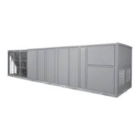
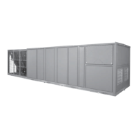
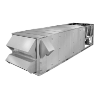
Shows dimensional drawings for unit configurations.
Illustrates curb layout configurations for unit installation.
Provides guidance for calculating electrical service requirements.
Explains power supply requirements and calculations.
Shows the wiring diagram for a single-point power connection.
Illustrates wiring with a non-fused disconnect switch.
Details the wiring diagram for dual-point power connections.
Describes filter types and condensate drain requirements.
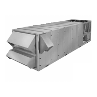
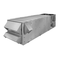
Details control wiring connections and installation of air hoods.
Covers specific control inputs/outputs and communication features.
Illustrates typical field control wiring configurations.
Discusses unit controller interface and pneumatic tubing installation.
Addresses air duct connection guidelines and noise control.
Provides instructions for gas line installation and combustion vent.
Explains the function and operation of crankcase heaters.
Details pre-start procedures and system checks before applying power.
Outlines checks to perform after applying power to the unit.
Guides through initial unit startup and performance checks.
Describes how to perform leak checks on the refrigerant system.
Details specific checks for gas heat sections before and after startup.
Explains how to adjust gas pressure for optimal heating performance.
Outlines the overall maintenance plan and monthly tasks.
Details procedures for cleaning condenser coils.
Details periodic maintenance tasks at different intervals.
Details periodic maintenance tasks performed annually.
Covers belt maintenance, tensioning, and replacement procedures.
Describes procedures for replacing filter driers.
Details steps for servicing forward curved fan components.
Details steps for replacing fan motors.
Details steps for servicing fan shaft bearings.
Explains different bearing locking mechanisms.
Details installation procedures for eccentric type bearings.
Specifies torque values for set-screws used in bearing installation.
Introduces control types and operational modes.
Details CV mode operations and control methods.
Explains thermostat integration and setpoints for CV units.
Describes operational modes for CV units based on occupancy.
Describes the integration and operation of space sensors.
Details cooling staging logic and operational modes.
Details heating staging logic and operational modes.
Explains control logic for stand-alone unit operation.
Explains VAV mode and its operational principles.
Details cooling staging logic specific to VAV units.
Details cooling operation with thermostat in VAV mode.
Covers unoccupied cooling operation with thermostat.
Explains VAV cooling control using space sensors.
Explains heating control via space sensor.
Details cooling operation in stand-alone mode.
Details heating operation in stand-alone mode.
Describes condenser fan control logic.
Explains the feature that prevents cooling below a set temperature.
Covers unit operation at low outdoor ambient temperatures.
Details VFD settings for condenser fan speed control.
Explains supply fan control logic for Constant Volume units.
Details VAV fan speed control based on duct static pressure.
Explains economizer modes and control strategies.
Details economizer control using dry bulb temperature.
Explains economizer control using single enthalpy.
Explains economizer control using dual enthalpy.
Describes economizer control integrated with a Building Automation System.
Specifies economizer set points for CV mode.
Specifies economizer set points for VAV mode.
Describes how economizer and compressor interact for cooling.
Explains the proportional-integral loop for economizer damper control.
Covers the economizer loading option for artificial load management.
Details the comfort ventilation mode for supply air temperature control.
Covers control strategies to prevent extreme supply air temperatures.
Explains how to use space sensors to adjust temperature set points.
Discusses fault handling when a space sensor input is lost.
Covers remote control input for varying set points.
Explains the feature for temporarily reducing compressor consumption.
Covers load shedding for reducing electrical consumption.
Explains how the system monitors filter status and triggers alarms.
Details how to enable metric unit conversion for temperature data.
Covers the Intelli-Start function for pre-occupancy temperature control.
Explains the function and sequence for morning warm-up.
Covers hydronic heating control and setpoints.
Explains the freeze protection function for hydronic heat.
Lists and describes available ventilation control methods.
Describes manual adjustment of the outdoor air damper.
Explains setting a fixed minimum ventilation position.
Details ventilation control based on indoor air quality (CO2).
Adjusts minimum ventilation based on low outdoor temperatures.
Details control strategies for exhaust fan operation.
Explains exhaust fan control using a Variable Frequency Drive.
Covers the function and sequence for pre-occupancy air purging.
Covers the operation of the energy recovery ventilator.
Explains the control's protection against low supply voltage.
Prevents heating operation when outdoor temperature is too high.
Describes the function of hot gas bypass for evaporator load.
Covers alarms generated based on space temperature trends.
Details the alarm condition for high supply air temperature in heating.
Covers alarms related to the economizer damper's minimum position.
Details the alarm condition for high supply air temperature in cooling.
Explains how to view and reset unit alarms.
Describes the physical interface and buttons on the unit controller.
Details button operations and how to interpret display codes.
Lists all programmable parameters, their ranges, and default settings.
Guides users on connecting the unit controller to a PC via Simplicity PC software.
Covers the installation of necessary software and hardware for PC connection.
Details the steps to establish communication between the controller and PC.
Explains how to navigate and view data through the Simplicity PC software.
Shows current readings from various unit sensors.
Displays configuration and status for economizer and exhaust systems.
Shows configuration and status related to unit fans.
Lists and describes parameters related to cooling operation configuration.
Displays the current operational status of cooling components.
Lists and describes parameters related to heating operation configuration.
Displays the current operational status of heating components.
Covers various system-level options and configurations.
Shows the status of unit outputs and accumulated runtimes.
Displays status of unit inputs and ventilation data.
Shows graphical representation and clock configuration.
Details how to program the unit's weekly operating schedule.
Explains how to program holiday schedules for the unit.
Shows active and historical alarm codes.
Guides on modifying unit parameters using the Simplicity PC software.
Defines each parameter available in the Simplicity Elite controller.
Details service procedures for analog inputs.
Explains the function and characteristics of temperature sensors.
Describes the function and installation of the duct pressure transducer.
Describes the function and installation of the building pressure transducer.
Describes the function and operation of the return fan pressure transducer.
Describes the function of the discharge pressure transducer.
Explains humidity sensor operation and output values.
Explains the function and operation of CO2 sensors.
Monitors and displays the status of gas heat sections.
Provides diagrams and tables for unit wiring connections.
Explains unit faults, lockout conditions, and their causes.
Lists and describes the unit's alarm codes.
Provides detailed descriptions for each alarm code.
Provides guidance for troubleshooting common system alarms.
Details troubleshooting for low pressure related alarms.
Details troubleshooting for limit switch alarms.
Details troubleshooting for gas heating related alarms.
Covers troubleshooting for space temperature sensor alarms.
Covers troubleshooting for supply air temperature sensor alarms.
Covers troubleshooting for return air temperature sensor alarms.
Covers troubleshooting for outdoor air temperature sensor alarms.
Covers troubleshooting for dirty filter switch alarms.
Covers troubleshooting for supply fan proving switch alarms.
Covers troubleshooting for microelectronics failure alarms.
Covers troubleshooting for supply fan overload alarms.
Covers troubleshooting for outdoor humidity sensor alarms.
Covers troubleshooting for return humidity sensor alarms.
Covers troubleshooting for IAQ (CO2) sensor alarms.
Covers troubleshooting for time clock error alarms.
Covers troubleshooting for space temperature offset alarms.
Covers troubleshooting for CV/VAV input alarms.
Covers troubleshooting for low voltage alarms.
Covers troubleshooting for smoke purge mode indications.
Covers troubleshooting for high duct static pressure alarms.
Covers troubleshooting for supply air temp cooling alarms.
Covers troubleshooting for supply air temp heating alarms.
Covers troubleshooting for economizer minimum position alarms.
Covers troubleshooting for space temperature trending alarms.
Covers troubleshooting for duct static low pressure alarms.
Covers troubleshooting for hot water coil freeze alarms.
| Brand | York |
|---|---|
| Model | ECO2 YPAL 050 |
| Category | Air Conditioner |
| Language | English |