Do you have a question about the York ECO R-407C and is the answer not in the manual?
Explains the structure and meaning of the product model number.
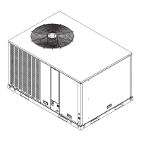
Guidelines for unit placement, rigging, and handling for safe installation.
Details economizers, coil protection, exhaust systems, and roof curbs.
Factors affecting unit sound levels and the process for unit selection.
Procedures for calculating Minimum Circuit Ampacity (MCA) and Maximum Overcurrent Protection (MOP).
Defines LOAD1, LOAD2, LOAD3, and LOAD4 for electrical service calculations.
Provides nominal voltage, RLA, and LRA for compressor models.
Describes the OptiLogic controller, user interface, and occupancy modes.
Explains economizer types and ventilation control sequences.
Covers exhaust fan control, low ambient operation, and smoke purge sequences.
Details VAV fan speed, cooling staging, and supply air temperature reset.
Wiring diagram and notes for a single-point power connection to the unit.
Wiring diagram for units with an optional non-fused disconnect switch.
Wiring diagram and notes for a dual-point power supply connection.
Wiring diagrams for thermostats, space sensors, and CO2 sensors.
Wiring for occupancy status, shutdown, and smoke purge inputs.
Wiring for VAV box control outputs, such as heat relay signals.
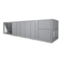
Covers unit construction, casing, fans, bearings, and general design.
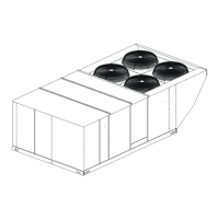
Details supply fans, air filters, and air inlet systems.
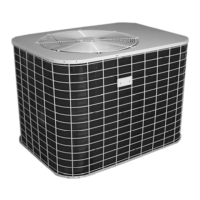
Covers compressors, coils, fans, piping, and unit power supply.
Details the controller, economizers, low ambient operation, and accessories.
| Brand | York |
|---|---|
| Model | ECO R-407C |
| Category | Air Conditioner |
| Language | English |