Do you have a question about the York eco2 050 and is the answer not in the manual?
Explanation of symbols used to indicate potential hazards in the manual.
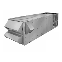
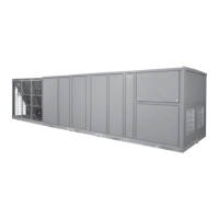
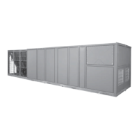
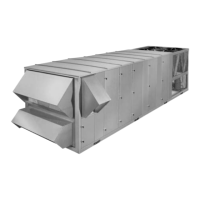
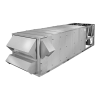
Details on efficient design, cooling/heating performance, and high-efficiency motors.
Explanation of IAQ features like drain pans, smart ventilation, and airflow measurement.
Certifications and compliance standards for unit installation.
Installation must conform to local building codes and industry standards.
Procedures for inspecting the unit for shipping or installation damage.
Guidelines for selecting a suitable unit location and required clearances.
Proper procedures for safely rigging and handling the unit.
Diagram showing required clearances for airflow and service access.
Provides physical dimensions and weights for 50-70 ton models.
Details fan, coil, and filter specifications for 50-70 ton models.
Lists physical data for 75-105 ton models, including weights and compressor data.
Lists motor data for supply, exhaust, and return fans, and control transformers.
Details compressor electrical data for R-22 and R-407C refrigerants.
Lists electrical data for electric heat options.
Specifies airflow limits and temperature conditions for operation.
Describes filter types, installation, and maintenance requirements.
Details condensate drain piping requirements and trap installation.
Information on field control wiring to CTB1 and CTB2.
Guidelines for thermostat installation and usage for unit control.
Guidelines for mounting and using space sensors for unit control.
Information on wiring the optional CO2 sensor for demand ventilation.
Describes the contact-closure input for occupancy status.
Describes the contact-closure input for emergency unit shutdown.
Input for initiating smoke purge sequences and their operation.
Output used to command VAV boxes to full open during smoke purge.
Describes the face damper for units with the Flexsys option.
Explains the function and wiring of the bypass damper for Flexsys units.
Describes the Roof-Link method for building automation system communication.
Details communication options with building automation systems.
Describes the adjustable differential pressure switch for dirty filters.
Wiring diagram for field control connections to CTB1.
Wiring diagram for Flexsys CTB2 connections and sensor inputs.
Guidelines for field wiring power supply, grounding, and disconnect switches.
Instructions for calculating electrical service requirements, MCA, and MOP.
Illustrates single-point power supply wiring connections to TB1.
Shows single-point power supply wiring with an optional non-fused disconnect.
Illustrates dual-point power supply wiring connections to TB1 and TB2.
Details pneumatic tubing requirements for static pressure transducers.
Information on plastic tubing for the duct static transducer.
Information on plastic tubing for the building pressure transducer.
Instructions for installing the factory-supplied static pressure probe.
General information and notes on roof curb assembly and installation.
Guidelines for connecting air ducts to the unit.
Explains the purpose and operation of crankcase heaters.
Checks to perform before applying power and starting the unit.
Detailed list of checks before the unit's initial start-up.
Checks to perform after applying power and before normal operation.
How to verify the correct rotation direction for scroll compressors.
Procedure for checking compressor oil levels.
Steps for placing the unit into operation after initial checks.
Information on refrigerant charge and adding refrigerant.
Procedures for checking and calculating superheat and subcooling.
Provides pressure-temperature data for R-22 refrigerant.
Provides saturation properties for R-407C refrigerant.
Method for calculating subcooling for R-22 systems.
Method for calculating superheat for R-22 systems.
Procedures for checking refrigerant circuits for leaks.
Pre-start checks for gas heat system components.
Performance data for gas heat stages, airflow, and temperature rise.
Monthly maintenance tasks including filter and linkage checks.
Procedures for checking compressor oil level and analysis.
Instructions for lubricating fan bearings and recommended grease.
Recommendation for keeping condenser coils clean.
Maintenance tasks including belt tension, sheave alignment, and unit inspection.
Periodic lubrication of motor bearings for longevity.
Adjusting belt tension and using belt cleaner.
Yearly maintenance tasks including fan wheel inspection and damper adjustments.
Information on belt tensioning using data plates and gauges.
Steps for replacing drive belts, emphasizing replacing as a set.
Procedure for replacing the filter/drier component in the refrigerant circuit.
Steps for removing and reassembling forward curved fan wheels.
Procedures for removing and installing a fan motor.
General information on removing and replacing fan shaft bearings.
Details on checking shaft, aligning, and securing bearings.
Explains the eccentric self-locking collar mechanism for bearings.
Classifies bearing locking devices including eccentric, concentric, and Skwezloc types.
Torque values for set screws used with bearings.
Details the sequence for staging compressors based on load demand.
Lists the sequence for staging compressors when increasing load.
Lists the sequence for staging compressors when decreasing load.
Explains staging based on compressor total run time for reliability.
Explains the operation of the supply fan, including minimum off time and overrun.
Details how the supply fan operates in Constant Volume mode.
Describes supply fan operation for VAV and Flexsys configurations.
Lists timeouts and delays applied to various unit functions.
Details control logic for Constant Volume units based on input priority.
How thermostat inputs control unit operation in CV mode.
Logic for staging compressors on during cooling demand.
Logic for staging compressors off during cooling demand.
How W1 and W2 thermostat inputs control heating operation.
How stepped heating is controlled by heat steps configuration.
Table showing how heating steps are assigned to stages.
Describes a sensor with an override button for unoccupied modes.
Describes a sensor with a slider for space setpoint adjustment.
Describes a sensor with both adjustment and override features.
How space temperature sensors control cooling operation.
Algorithm for space sensor cooling when economizer is not suitable.
Algorithm for space sensor cooling when economizer is suitable.
Algorithm for space sensor control of stepped heating.
Algorithm for space sensor control of hydronic heating.
How thermostats are used for SAT reset control in VAV mode.
When space sensors are used for control in VAV mode.
Standalone VAV operation when thermostat or space sensor is unavailable.
Common functions across VAV operating modes like heating and cooling.
Controls occupied heating with a space sensor.
Controls unoccupied heating with a space sensor.
Controls occupied cooling with a space sensor.
Controls unoccupied cooling with a space sensor.
Conditions for initiating heating operation in standalone mode.
Describes when the unit remains shut down in unoccupied heating.
Conditions for occupied cooling in standalone operation.
Describes when the unit remains shut down in unoccupied cooling.
Algorithm for maintaining SAT setpoint in VAV cooling.
Algorithm for controlling supply duct static pressure.
Algorithm for VAV heating/cooling control using a space sensor.
Describes the Morning Warm Up operation sequence and conditions.
Details VAV supply air tempering operation with various heat types.
How proportional heat is used for supply air tempering.
How staged heat is used for supply air tempering.
Conditions required for economizer operation.
Methods for determining economizer suitability based on sensors.
SAT setpoints used during cooling with economizer operation.
PI control algorithm for SAT management using economizer.
Controls compressor operation in conjunction with the economizer.
Details the Economizer Loading Operation function and its parameters.
Notes on using the SAT Econo Loading parameter.
Describes various ventilation options and their control.
Common method for ventilation control using fixed minimum OA damper position.
Operation using air measurement stations for outdoor air control.
Approach using a small AMS for minimum required OA flow measurement.
Approach using a large AMS for full OA flow measurement.
Parameters for setting up air measuring stations (area and K-factor).
Process for auto-zeroing OA flow sensors to minimize drift.
How to correct airflow measurements using air balancer data.
Lists area and K-factor values for air measuring stations.
Diagram illustrating minimum flow measurement arrangement.
Airflow control when economizer is not available.
Airflow control when economizer is available.
Diagram showing economizer sequence for minimum flow.
Description of full flow measurement equipment and arrangement.
Airflow control when economizer is not available for full flow.
Diagram for full flow measurement without economizer.
Airflow control when economizer is available for full flow.
Diagram for full flow measurement with economizer sequence.
Control sequence to adjust ventilation based on indoor air quality.
Details about IAQ sensors and their connection for Demand Ventilation.
Describes the algorithm used for Demand Ventilation control.
Operation of mechanical refrigeration at low ambient temperatures.
Diagram illustrating hardware required for low ambient operation.
Graph showing the proportional band for condensing pressure control.
Operation of mechanical refrigeration at low ambient temperatures.
Safety monitoring for communication failures and transducer issues.
Note on configuring excessive SAT settings.
Control of building pressure using exhaust fan configurations.
On/Off exhaust fan control based on outdoor air damper position.
On/Off exhaust fan control based on building pressure.
Diagram illustrating OAD position control for exhaust fan.
Diagram illustrating building pressure control for exhaust fan.
Graph showing the proportional band for exhaust fan control.
Diagram illustrating proportional exhaust fan control.
Uses building pressure to vary VFD exhaust fan speed and airflow.
Features of the unit's time-of-day clock and calendar for scheduling.
Explains the function of the Changeover Relay (COR) for staging.
Control logic for unloading compressors based on discharge pressure.
Operation of comfort ventilation in CV units with specific conditions.
How economizer controls SAT during comfort ventilation.
Algorithm for staging heating or cooling during comfort ventilation.
Freeze protection for hot water systems using return air monitoring.
Describes five selectable options for smoke purge operation.
Explanation of different return fan operation modes.
Configuration for applications where supply fan performance is limited.
Configuration for applications with supply fan limitations and exhaust damper.
Configuration for VAV supply fan with manual outside air control.
Configuration with VAV supply fan and motorized exhaust damper.
Configuration with modulating economizer, VFD supply fan, and no exhaust.
Configuration with modulating economizer, VFD supply fan, and motorized exhaust.
Explains modulating gas heat operation with multiple stages.
Diagram illustrating the staging sequence for modulating gas heat.
Describes the operation of compressor control components and systems.
Describes Flexsys VAV operation, including sensors and bypass duct.
Overview of Flexsys operation, air mixing, and sensor inputs.
Formulas for calculating bypass damper setpoints and percentages.
Graph illustrating bypass damper setpoints and drive logic.
Overview of the control center's function, keypad, and display.
Instructions on using keys to navigate through menu items.
How to navigate and access stored historical unit data.
Accessing information about the unit's current operational status.
Displays general unit status, type, and operational mode.
Shows unit status related to date, time, and control source.
Displays fan status, compressor system status, and heat system status.
Shows economizer system type and status, and ventilation configurations.
Displays ventilation system type and status, and filter status.
Shows thermostat and occupancy input status.
Displays the status of the G input signal.
Displays compressor status for systems 1, 2, and 3.
Shows compressor suction and discharge pressures.
Displays compressor staging information.
Shows outdoor air temperature, humidity, and enthalpy.
Displays return air temperature, humidity, and enthalpy.
Shows supply air temperature and setpoint.
Displays supply duct pressure and setpoint.
Shows space temperature and setpoint.
Displays building pressure and setpoint.
Shows outdoor air damper position and minimum position.
Displays outdoor air damper positions 2 and 3.
Shows outdoor air damper flow for section 1.
Shows outdoor air damper flow for section 2.
Displays total outdoor air damper flow and setpoint.
Shows demand ventilation sensor value and setpoint.
Displays Flexsys supply air temperature and setpoint.
Shows Flexsys humidity, dewpoint, and slab temperature.
Displays Flexsys bypass damper position.
Shows Flexsys bypass air active percentage and setpoint.
Displays Rooflink status and smoke purge mode.
Accessing and modifying general setpoint data.
Accessing and modifying general unit setup data.
General setup options, including language and measurement units.
General setup display showing language and setting.
Econo/Exhaust system settings, including economizer enable.
Navigating and displaying weekly and holiday schedules.
Accessing and modifying unit configuration data.
Heat/Cool system and freezestat settings.
Accessing service-related information and parameters.
Displays accumulated run times for compressors in System 1.
Shows accumulated run times for supply and exhaust fans.
Displays the number of starts for compressors in System 1.
Shows the status of cooling and heating lockouts based on OAT.
Displays modes enabled for cooling and heating.
Shows the status of compressor safety chains.
Shows economizer activity and SAT setpoint.
Shows air balancer calculated airflow for AMS #1.
Displays AMS #1 controller measured airflow at balance.
Shows application and revision number.
Displays economizer tuning parameters.
Accessing unit error histories and troubleshooting equipment problems.
Shows fault description, priority, status, and date/time.
Lists fault text descriptions and their classifications.
Lists data points associated with fault history entries.
Parameters related to the current date and time entry.
User-programmable setpoints intended for field configuration.
Setpoint for unoccupied heating mode.
Setpoint for unoccupied cooling mode.
Setpoint for occupied heating in constant volume units.
Setpoint for occupied cooling in constant volume units.
SAT setpoint for first stage cooling in VAV mode.
SAT setpoint for second stage cooling in VAV mode.
Setpoint used to reset SAT based on space or outside air temperature.
Setpoint for supply duct static pressure control.
Setpoint for building pressure control during power exhaust.
SAT setpoint for first stage cooling during economizer operation.
SAT setpoint for second stage cooling during economizer operation.
SAT setpoint for economizer loading during heating.
Limit for outside air enthalpy availability for cooling.
High SAT limit setpoint for comfort ventilation mode.
Low SAT limit setpoint for comfort ventilation mode.
Return air temperature setpoint for morning warm-up.
SAT setpoint for first stage hydronic or modulating gas heat.
SAT setpoint for second stage hydronic or modulating gas heat.
Minimum OA damper position for occupied mode at full supply fan speed.
Minimum OA damper position for VAV at reduced fan speed.
Maximum IAQ (CO2) level allowed for ventilation control.
Airflow setpoint for controlling the outside air damper.
Mixed supply air temperature setpoint for FlexSys units.
Determines reset of evaporator discharge air temperature setpoint.
General unit configuration settings.
Enables or disables the use of a space temperature sensor.
Duration the unit operates in unoccupied override mode.
Offset value to adjust the space temperature setpoint.
Controls supply fan operation based on space sensor in CV mode.
Enables or disables the use of the return air temperature sensor.
Parameter used to generate a fault if space temperature deviates from setpoint.
Time duration for space temperature deviation before a fault is declared.
Enables or disables low ambient operation.
Enables sensor consistency tests for system reliability.
Settings related to the unit's heating and cooling system configuration.
Setting for excessive SAT monitoring and tripping for cooling.
Setting for excessive SAT monitoring for heating.
Controls the operation of a reverse-acting heat valve.
Enables or disables the unit's cooling operation.
Enables or disables the unit's heating operation.
Outside air temperature setpoint to lock out heating.
Outside air temperature setpoint to lock out cooling.
Setpoint for cooling SAT alarm when compressors are running.
Setpoint for heating SAT alarm when heating stages are operating.
Parameters specific to Variable Air Volume system configuration.
Static pressure setpoint to shut down the unit if exceeded.
Allows VAV occupied heating based on thermostat or space temperature.
Resets SAT setpoint based on OAT instead of space temperature.
Enables SAT tempering for stability in heating or cooling.
Configures VAV mode to use a thermostat or space sensor.
Adjusts compressor staging offset for VAV units.
Enables evaporator discharge air temperature reset for FlexSys.
Exhaust damper position to turn on the exhaust fan.
Exhaust damper position to turn off the exhaust fan.
Economizer damper position to turn on the exhaust fan.
Economizer damper position to turn off the exhaust fan.
Enables the outside air humidity sensor for enthalpy control.
Enables the return air humidity sensor for enthalpy control.
Control band for building pressure control.
Enables or disables economizer operation.
Uses economizer loading to control excessive SAT.
Enables or disables the power exhaust system.
Settings related to ventilation control and airflow measurement.
Enables active control of the outside air damper based on airflow.
Enables comfort ventilation operation in CV units.
Maximum economizer damper position for comfort ventilation.
Enables the IAQ sensor for economizer control via demand ventilation.
Specifies the full range (span) for the installed IAQ sensor.
Maximum Demand Ventilation Multiplier limit.
Unit altitude above sea level for airflow control calculations.
Morning Warm-Up feature and its activation conditions.
How Morning Warm Up is enabled and started in networked or scheduled applications.
Maximum time duration for Morning Warm Up operation.
Initiates purge based on schedule and OAT limits.
Programmable time of day to start purge for each day.
Upper limit for purge using 100% outdoor air.
Lower limit for purge using 100% outdoor air.
Enables/disables smoke purge and selects control sequence.
Uses internal clock and schedule for unit operations.
Entry for time-programmed unit operation schedule.
Entry for holiday dates for time-programmed operation.
Factory-programmed setpoints that should not be changed in the field.
General unit configuration settings.
Selects the rooftop unit type (CV, VAV, Flexsys).
Configures monitoring of the dirty filter switch input.
Command to set compressor Anti Short Cycle Delays to 30 seconds.
Initiates a test sequence for compressors and heating stages.
Test used only for factory testing, not for field use.
Settings related to the unit's heating and cooling system configuration.
Specifies the number of compressors available in the unit.
Specifies the number of heating steps available for the unit.
Configures hot water freeze protection monitoring.
Indicates if pressure transducer packages are installed and their system.
Configures low ambient hardware installation for refrigeration systems.
Discharge pressure control setpoint for low ambient operation.
Discharge pressure setpoint to unload compressor systems.
Resets accumulated compressor run times to zero.
Settings for monitoring and tripping on excessive Supply Air Temperature.
Indicates if equipment for SAT tempering is installed.
Low limit for SAT during mechanical cooling with one compressor.
Low limit for SAT during mechanical cooling with multiple compressors.
High limit for SAT during heating operation.
Settings related to economizer and exhaust fan control.
Specifies the type of power exhaust system installed.
Indicates if economizer hardware is installed on the unit.
Selects the outside airflow measurement equipment (Minimum or Full).
Parameters for AMS #1, used for Minimum and Full options.
Cross-sectional area used to calculate airflow through AMS #1.
Corrects for AMS measurement error and test/balance adjustments.
Parameters viewable by service personnel for run-timer adjustments.
Compressor runtimes should not be changed, used for staging control.
Number of compressor starts, updated when a compressor is replaced.
Fan runtimes can be reset to zero when a fan is replaced.
Explanation of how to change changeable parameters referred to as setpoints.
Entering edit mode to change setpoints on the display.
Explains password levels and entry procedures for OCC functions.
Lists all changeable parameters, their units, default values, and ranges.
Continues the list of changeable parameters and their OCC key.
Continues the list of changeable parameters and their OCC key.
Information related to servicing the unit, including the Primary Unit Controller.
Description of the factory-mounted microprocessor-based controller.
Shows the IO layout and connections to the Primary Unit Controller.
Lists descriptions of various inputs and outputs and their connections.
Binary output relays and associated LEDs on the Primary Unit Controller.
Diagram showing the I/O connection map of the Primary Unit Controller.
Illustration of binary LED designations on the Primary Unit Controller.
Describes the control operation of the sixteen binary inputs.
Status inputs for compressor safety chains, including high/low pressure safeties.
Settings for high-pressure switches.
Settings for low-pressure switches.
Explanation of trip counters for compressor safety circuits.
Status inputs for furnace modules, reserved for future use.
Monitors the thermostat "G" or fan output for supply fan control.
Used to determine occupied or unoccupied control modes.
Monitored by the control to interpret shutdown conditions.
Monitored by the control to interpret smoke purge requirements.
Verifies supply fan status using an airflow switch.
Describes the fault condition when the supply fan is off but the status input is present.
Indicates if filters are dirty via a differential pressure switch.
Input not used with smart relay; monitored externally.
Monitors hot water freezestat input for freeze protection.
Verifies the status of changeover relays for heating/cooling commands.
Signals to the control that the VFD has been bypassed.
Describes the operation of the thirteen analog inputs for monitoring.
Senses and converts static pressure in the supply duct to a DC voltage.
Senses and converts static pressure in the building to a DC voltage.
Shows output voltage vs. differential input pressure for duct transducers.
Describes the optional air measuring station and its transducers.
Senses and converts discharge pressure to a DC voltage for control.
Shows output voltage vs. differential input pressure for building transducers.
Shows output voltage vs. differential input pressure for AMS transducers.
Shows output voltage vs. input pressure for discharge transducers.
Senses and converts suction pressure to a DC voltage for control.
Describes the variable speed drive for condenser fan motors in low ambient conditions.
Shows output voltage vs. input pressure for suction transducers.
Diagram showing the I/O connection map of the Primary Unit Controller.
Lists I/O names, signal levels, and application for MOD-UNT controller.
Describes the CO2 sensor used with Demand Ventilation for air quality control.
Shows CO2 levels and corresponding output voltages.
Describes the combined humidity and temperature sensor.
Shows relative humidity and corresponding output voltages.
Explains the six analog outputs used for actuator control.
Describes the ten binary outputs that switch 24 VAC to relays.
Interface board for connecting thermostats to the Primary Unit Controller.
Shows voltage outputs for thermostat inputs.
Describes how certain binary inputs are routed through the interface board.
Lists thermostat interface board connections, functions, and MOD DCU connections.
Lists all inputs and outputs, their types, signal levels, and applications.
Continues the list of inputs and outputs with their applications.
Explains fault categories (Trouble, Alarm) and their impact on unit operation.
How the unit stores and displays faults, and the role of the System Alarm LED.
Classifies faults into Trouble and Alarm categories.
Procedures for clearing faults, including manual and auto resets.
Declares a fault if communication with the MOD-UNT is lost.
Monitors analog inputs for reliability and range compliance.
Monitors temperature inputs for reliability and detects open or shorted conditions.
Compares voltage inputs to allowed ranges and detects unreliability.
Describes the safety switch for preventing excessive negative return pressure.
Lists fault titles, when they are set, reset conditions, and general status.
Continues the fault description table with additional faults and actions.
Continues the fault description table with additional faults and actions.
Notes clarifying fault descriptions, status indicators, and fault handling.
Elementary diagram for YPAL MOD-B/C power side, single point power.
Elementary diagram for 50-65 ton YPAL MOD-B/C power side, single point power with return fan.
Elementary diagram for 70-105 ton YPAL MOD-B/C power side, single point power with return fan.
Elementary diagram for 70-105 ton YPAL MOD-B/C power side, dual point power with return fan.
Elementary diagram for 50-65 ton YPAL MOD-B/C power side, dual point power with return fan.
Wiring diagram for Class 1 control of 50-65 ton YPAL MOD-C units.
Wiring diagram for Class 1 control of 70-105 ton YPAL MOD-C units.
Wiring diagram for Class 2 control of 50-65 ton YPAL MOD-C units.
Wiring diagram for Class 2 control of 50-65 ton YPAL MOD-C units.
Wiring diagram for Class 2 control of 50-65 ton units with return fan.
Wiring diagram for Class 2 control of 50-65 ton units.
Wiring diagram for Class 2 control of 70-105 ton units with return fan.
Wiring diagram for Class 2 control of 50-65 ton units.
Component map of the power panel for 50-65 ton MOD C units.
Component map of the power panel for 70-85 ton MOD C units.
Component map of the power panel for 70-105 ton MOD C units.
Component map of the power panel for 70-105 ton MOD C units.
Component map of the CV fan subpanel for units without exhaust fans.
Component map of the CV fan subpanel for units with CV exhaust fans.
Component map of the CV fan subpanel for units with VAV exhaust fans.
Component map of the VAV fan subpanel for units without exhaust fans.
Component map of the VAV fan subpanel for units with CV exhaust fans.
Component map of the VAV fan subpanel for units with VAV exhaust fans.
Component map of the fuse standoff plate for units without gas heat.
Component map of the fuse standoff plate for units with gas heat (200/230V).
Component map of the fuse standoff plate for units with gas heat (380-575V).
Fuse standoff plate component map for various voltage units with gas heat.
Elementary diagram for optional gas heat power wiring.
Wiring diagram for gas heat controls, including modules and flame sensors.
Wiring diagram for gas heat controls, detailing modules and components.
Wiring diagram for gas heat controls, showing furnace configuration setup.
Wiring diagram for electric heat controls across multiple ton ranges.
Wiring diagram for Class 1 control of 50-65 ton YPAL MOD-C units.
Wiring diagram for modulating gas heat controls on 50-65 ton units.
Wiring diagram for modulating gas heat controls on 70-105 ton units.
| Brand | York |
|---|---|
| Model | eco2 050 |
| Category | Air Conditioner |
| Language | English |