67
YORK INTERNATIONAL
FORM 100.50-NOM1 (604)
5
5
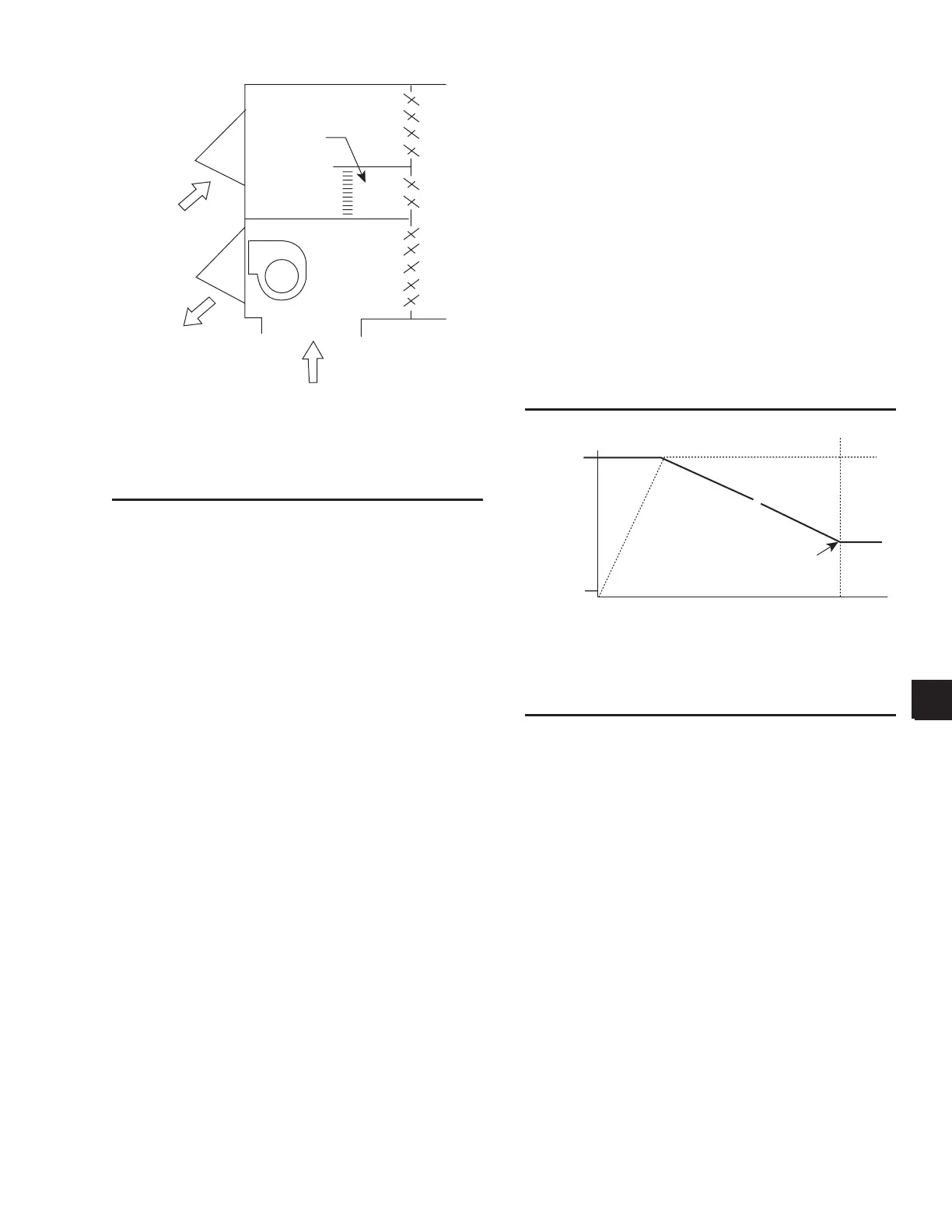
FIG. 32 – MINIMUM FLOW MEASUREMENT
ARRANGEMENT
A differential pressure transmitter will be used to mea-
sure a differential pressure across the AMS, which will
correspond to an average velocity through the AMS. The
measured dif fer en tial pressure (read at an ap pro pri ate
Analog Input) will be con vert ed by the con trol ler to an
approximate ß ow. The entered data is for AMS #1.
When the unit is in the unoccupied mode of operation,
dampers #1 and #2 will be 100% closed and damper #3
will be 100% open.
Airfl ow Control - Economizer Not Available
When the unit is in the occupied mode of operation,
and:
• Airfl ow Meas Confi g = 1 (minimum)
• Economizer Enable = OFF, or
• Economizer Enable = ON and econ o miz er con di -
tions are not available:
Damper #2 will be closed and the following control of
Dampers #1 and #3 will be used:
• On entering the airß ow control mode of op er a tion,
Damp er #3 (return air damper) is 100% open.
• An appropriate control algorithm will be used to
mod u late the position of Damper #1 (out door air)
to maintain the Minimum Flow Setpoint.
• When the Minimum Flow Setpoint cannot be
achieved with Damper #3 (Return Air Damp er)
100% open, the RA Damper will be mod u lat ed
closed so that the Min i mum Flow Setpoint is
achieved.
• The maximum closure of Damper #3 will be
that po si tion resulting in the maximum allowed
airß ow velocity through the AMS and Damper
#1 or 1500 fpm. Divide the airß ow by the area
in table 18 to determine velocity.
The following Þ gure is a representation of the damper
versus airß ow operation.
Air Flow Control - Economizer Available
When the unit is in the occupied mode of operation,
and:
• Airfl ow Meas Confi g = 1 (minimum)
• Economizer Enable = ON and econ o miz er con di -
tions are available:
Damper #1, #2 and #3 will be controlled through an
ap pro pri ate algorithm to meet the following two re-
quire ments:
• The measured outdoor airß ow is => Minimum Flow
Setpoint.
• The outdoor dampers are mod u lat ed to meet the
requirements of economizer operation.
Exhaust
Air
utside
Air
#
#
#
25%
Measuring
Station
LD06563
FIG. 33 – CONTROL FOR MINIMUM AMS –
ECONOMIZER NOT AVAILABLE
pen (100%)
Damper
Position
losed (0%)
0 CFM
MAX CFM
OA AMS/Damper Air Flow
Velocity => Maximum Allowed
#1
#3
LD06564
 Loading...