EasyManua.ls Logo

York F*FP User Manual

York F*FP
16 pages
To Next Page IconTo Next Page
Page #1 background imageLoading...
Page #1 background image
TECHNICAL GUIDE
SINGLE PIECE AIR HANDLERS
FOR USE WITH SPLIT-SYSTEM
COOLING & HEAT PUMPS
HEAT PUMP MODELS:
F*FP
VARIABLE SPEED MODEL:
F*FV
Due to continuous product improvement, specifications
are subject to change without notice.
V
isit us on the web at www.york.com
Additional rating information can be found at
www.ari.org/aridirectory.
ISO 9001
Certified Quality
Management System
295421-YTG-B-0707
FOR DISTRIBUTION USE ONLY - NOT TO BE USED AT POINT OF RETAIL SALE
DESCRIPTION
This fan coil unit provides the flexibility for installation in any
upflow or horizontal application. These versatile models may
be used for split-system cooling or heat pump operation.
Compact cabinets along with return air options in both the
upflow and horizontal positions allow this unit to fit into tight
spaces such as attics, crawl spaces, and closets.
NOTE: For matching condensing units and performance
data, refer to condenser technical guides.
FEATURES
CABINET -The compact and sturdy cabinet is protected with
a durable, attractive finish to prevent rust. The cabinet is also
insulated to prevent cabinet sweating. F*FP and F*FV mod-
els have 3/4 inch insulation.
BLOWERS - Blowers are sized to circulate air both quietly
and efficiently. The direct-drive, multi-speed motors provide a
selection of air volume to match any application. Motor
speeds may be selected via quick connect terminal at the
motor. Slide-out blower/motor assemblies provide for easy
servicing.
COILS - Using the latest in heat transfer technology, the rifled
tube coil/aluminum fin coils produce high performance ratings
and provide long lasting quality. The coils are capable of bot-
tom return air in the upflow position, and right or left end
return air in the horizontal position.
FACTORY INSTALLED TXV - Air handler models F*FP and
F*FV have factory installed TXV metering device.
ELECTRIC HEATERS - Models providing up to 25kw of heat
are available as field installed accessories. Electric heaters
are available in both single and three phase.
EASY INSTALLATION - These fan coil units are designed to
provide the lowest total installation cost. Accessible color
coded control wiring, top and side power wiring knockouts,
easy to install drain connections and electric heaters all com-
bine to minimize installed cost on every job.
CONTROL BOARD - The control board is equipped with low
voltage terminal strips for easy installation. The control board
is also equipped with plug-in receptacles for the auxiliary
heaters.
Question and Answer IconNeed help?

Do you have a question about the York F*FP and is the answer not in the manual?

York F*FP Specifications

General IconGeneral
BrandYork
ModelF*FP
CategoryHeat Pump
LanguageEnglish

Summary

YORK Air Handler Technical Guide

Unit Introduction and Key Features

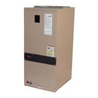
Provides a general overview of the fan coil unit, its applications, and significant features like cabinet, blowers, and coils.

Installation and Control Features

Details the unit's easy installation aspects and the functionality of its control board.

Unit Dimensions and Performance Data

Physical Dimensions and Wiring Details

Presents detailed physical dimensions, wiring knockout locations, and refrigerant line sizes for various models.

Coil Specifications and Cooling Capacity

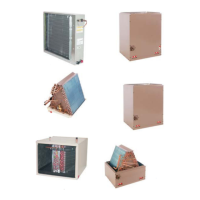
Lists coil technical data, including tube type and fins per inch, and cooling capacity (MBH).

Airflow, Accessories, and Operational Limits

Extended Airflow Data for Heat Pumps

Provides detailed airflow data for 230V and 208V heat pump models at various static pressures.

Optional Accessories and Operational Limitations

Describes optional kits, accessories, and key operational limitations such as voltage and air flow requirements.

Capacity Factor Adjustments for CFM

Offers factors to adjust rated CFM based on actual capacity requirements for airflow optimization.

Variable Speed and Electric Heat Operation

CFM Selection and Delay Profile Settings

Explains CFM selection for F4FV variable speed models and describes comfort settings for blower operation.

Electric Heat CFM Configuration Options

Lists CFM values and tap selections for various electric heat operation modes.

Physical and Electrical Specifications

Unit Physical Characteristics and Cooling Electrical Data

Summarizes physical characteristics and electrical data for cooling operation, including amps, ampacity, and wire size.

Heat Pump Electrical Data and Conversions

Provides electrical data for 208/230V heat pump models and includes KW/MBH conversion factors.

Electrical Data for 1Ø and 3Ø Power Supplies

Single Source Power Supply Electrical Data (1Ø)

Details electrical data for single-source 1Ø power supply, including ampacity and wire size.

Multi-Source 1Ø and 3Ø Power Supply Data

Electrical data for multi-source 1Ø and 3Ø power supplies, covering ampacity and wire sizing.

Three Phase Single Source Power Supply Data

Electrical data for three-phase single-source power supply, including ampacity and wire size.

Field Wiring and Installation Guides

Wiring Diagrams for Cooling and Heater Kits

Illustrates field wiring connections for cooling-only and with heater kit applications.

Wiring Diagrams for Electric Heat and Heat Pumps

Shows wiring diagrams for electric heat and single-stage heat pump configurations.

Typical Installation and Application Layouts

Illustrates general installation setup and common application configurations like upflow and horizontal.

Related product manuals