Do you have a question about the York FCHP090 and is the answer not in the manual?
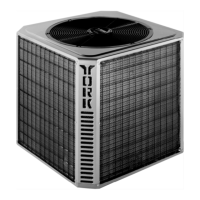
Covers indoor unit installation and refers to the matching outdoor unit manual.
Specifies compliance with national and local safety codes for unit installation.
Details requirements for indoor unit placement within the building structure.
Provides instructions and warnings for safely moving and handling the unit.
Outlines minimum required clearances for proper unit operation and service.
Explains conversion procedures for vertical or horizontal unit installation.
Details design and installation of ductwork according to national and local codes.
Discusses procedures for installing refrigerant lines to ensure a clean, dry system.
Explains the necessity of trapping the drain line and the required trap depth.
Guides on adjusting blower RPM based on CFM, accessories, and static resistance.
Install wiring per NEC/local codes, ground unit, and route wires through knockouts.
Check/reverse motor rotation; refer to electric heat accessory instructions.
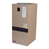
This document describes the installation, operation, and maintenance of Split-System Heat Pumps Indoor Units, specifically models FCHP090 and FDHP120.
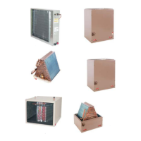
These units are completely assembled indoor units designed for use in split-system heat pump applications. They include a well-insulated cabinet, a copper tube/aluminum fin coil, throw-away filters, a centrifugal blower, a blower motor, an adjustable V-belt drive, a blower motor contactor, and a small holding charge of an inert gas. They also feature a filter-drier, an expansion valve, and a distributor for the cooling cycle, plus a check valve for proper refrigerant flow during both cooling and heating cycles. These units are designed to provide conditioned air for indoor spaces, working in conjunction with a matching outdoor unit.