EasyManua.ls Logo

York H*DB012 - 76 User Manual

York H*DB012 - 76
16 pages
To Next Page IconTo Next Page
Page #1 background imageLoading...
Page #1 background image
CONTENTS
GENERAL
. . . . . . . . . . . . . . . . . . . . . . . . . . . . . . . . . . . . .
2
NOMENCLATURE
. . . . . . . . . . . . . . . . . . . . . . . . . . .
2
SAFETY
. . . . . . . . . . . . . . . . . . . . . . . . . . . . . . . . . . .
2
INSPECTION
. . . . . . . . . . . . . . . . . . . . . . . . . . . . . . .
2
LIMITATIONS
. . . . . . . . . . . . . . . . . . . . . . . . . . . . . . .
2
LOCATION
. . . . . . . . . . . . . . . . . . . . . . . . . . . . . . . . . . . .
3
GROUND INSTALLATION
3
ROOF INSTALLATION
. . . . . . . . . . . . . . . . . . . . . . . .
3
UNIT PLACEMENT
. . . . . . . . . . . . . . . . . . . . . . . . . . . . . .
3
VERIFY INDOOR REFRIGERANT ORIFICE
. . . . . . .
4
INSTALLATIONS REQUIRING TXV
. . . . . . . . . . . . .
4
PIPING CONNECTIONS
. . . . . . . . . . . . . . . . . . . . . . . . . .
5
PRECAUTIONS DURING LINE INSTALLATION
. . . .
5
PRECAUTIONS DURING BRAZING OF LINES
. . . . .
6
PRECAUTIONS DURING BRAZING
ANGLE VALVE
. . . . . . . . . . . . . . . . . . . . . . . . . .
6 & 7
GENERAL INFORMATION & GROUNDING
. . . . . . . . . .
8
FIELD CONNECTIONS POWER WIRING
. . . . . . . . . . . .
8
FIELD CONNECTIONS CONTROL WIRING
. . . . . . . . . .
8
SYSTEM CHARGE
. . . . . . . . . . . . . . . . . . . . . . . . . .
8
MEASUREMENT METHOD
. . . . . . . . . . . . . . . . . . . .
9
SUPERHEAT CHARGING METHOD
. . . . . . . . . . . .
9
SYSTEM START-UP
. . . . . . . . . . . . . . . . . . . . . . . . . . . . .
9
ENERGIZE CRANKCASE HEATER
. . . . . . . . . . . . .
9
SYSTEM CONTROLLER - HDB076 ONLY
. . . . . . .
13
INSTRUCTING THE OWNER
. . . . . . . . . . . . . . . . . .
13
INDICATIONS OF PROPER OPERATION
. . . . . . .
13
MAINTENANCE
. . . . . . . . . . . . . . . . . . . . . . . . . . . .
13
INSTALLATION
INSTRUCTIONS
CAUTION:
READ ALL SAFETY GUIDES BEFORE
YOU BEGIN TO INSTALL YOUR UNIT.
SAVE THIS MANUAL
STELLAR
AIR CONDITIONING UNIT
SPLIT-SYSTEM COOLING
MODELS:
10 SEER
H*DB012 - 76
11 SEER
H*DE024 - 60
12 SEER
H*DH018 - 60
50 Hz
H*DA018-076
035-14562-000 REV A (
999) Form 550.38-N1Y (999)
Question and Answer IconNeed help?

Do you have a question about the York H*DB012 - 76 and is the answer not in the manual?

York H*DB012 - 76 Specifications

General IconGeneral
BrandYork
ModelH*DB012 - 76
CategoryAir Conditioner
LanguageEnglish

Summary

General Unit Information

Nomenclature and Product Codes

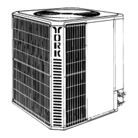
Explains unit identification codes and product details for installation.

Safety Precautions

Crucial warnings and cautions for safe installation and operation of the unit.

Inspection Guidelines

Guidelines for inspecting the unit for damage upon arrival and transit.

Operational Limitations

Outlines operational constraints and installation restrictions for the air conditioning unit.

Location and Unit Placement

Ground Installation Procedures

Instructions for installing the unit on a stable ground base, ensuring levelness and isolation.

Roof Installation Considerations

Considerations for structural support and sound isolation when installing on a roof.

Unit Placement Steps

Detailed steps for positioning the unit on the base, including grommet use and wall penetration.

Refrigerant Orifice and TXV Installation

Verify Indoor Refrigerant Orifice

Procedure to determine and verify the correct orifice for the indoor coil match.

TXV Kit Installation

Basic steps for installing a Thermal Expansion Valve (TXV) kit for specific system matches.

Piping Connections and Brazing

Precautions During Line Installation

Guidelines for safe and proper installation of refrigerant lines, minimizing bends and avoiding kinks.

Precautions During Line Brazing

Safety measures and techniques for brazing refrigerant lines using approved materials.

Precautions During Angle Valve Brazing

Specific precautions for brazing angle valves to prevent heat damage and ensure proper seal.

Electrical Connections and System Charge

General Information and Grounding

Ensuring electrical supply meets specifications and proper grounding methods.

Field Power Wiring

Instructions for making power wiring connections, including disconnect switch and wire sizing.

Field Control Wiring

Instructions for making low voltage control wiring connections to the unit.

System Charge Calculation

Determining the total system refrigerant charge based on unit, coil, and line set.

System Startup and Operation

Refrigerant Measurement Method

Procedure for adding refrigerant using a calibrated charging cylinder or weighing device.

Superheat Charging Method

Method for charging refrigerant based on superheat calculation for system optimization.

Energize Crankcase Heater

Instructions for energizing the compressor crankcase heater to prevent oil migration.

System Controller and Owner Information

System Controller HDB076 Operation

Details on the operating modes and functions of the HDB076 system controller.

Instructing the Owner

Guidance for educating the owner on unit operation, maintenance, and warranty.

Indications of Proper Operation

Checks to verify the system is operating correctly, including fan and air discharge.

Unit Maintenance Procedures

Recommended procedures for maintaining the unit's performance, including coil cleaning.

Related product manuals