ate the system down to at least 500 microns to eliminate
contamination and moisture in the system.
” on page 9 for checking and
GENERAL INFORMATION & GROUNDING
Check the electrical supply to be sure that it meets the values
specified on the unit nameplate and wiring label.
Power wiring, control (low voltage) wiring, disconnect
switches and over current protection to be supplied by the
installer. Wire size should be sized per NEC requirements.
The complete connection diagram and schematic wiring label
is located on the inside surface of the unit electrical box cover
FIELD CONNECTIONS POWER WIRING
Install the proper size weatherproof disconnect switch
outdoors and within sight of the unit.
Run power wiring from the disconnect switch to the unit.
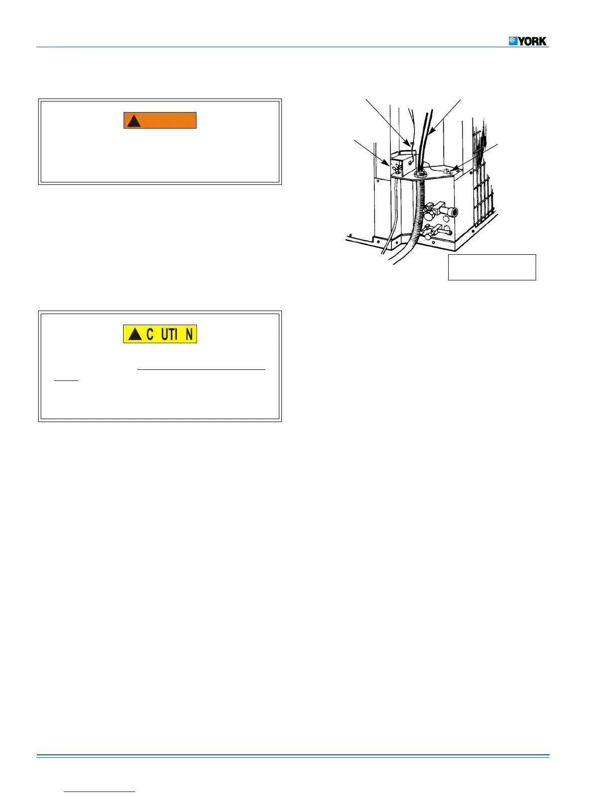
Remove the control box cover to gain access to the unit
wiring. Route wires from disconnect through power wir-
ing opening provided and into the unit control box as
Install the proper size time-delay fuses or circuit breaker,
and make the power supply connections.
Energize the crankcase heater to save time by preheat-
ing the compressor oil while the remaining installation is
FIELD CONNECTIONS CONTROL WIRING
Route low voltage wiring into bottom of control box as
shown in Figure 7. Make low voltage wiring connections
inside the junction box per Figures 8, 9, 10 or 11.
The complete connection diagram and schematic wiring
label is located on the inside surface of the unit electrical
All field wiring to be in accordance with national electrical
codes (NEC) and/or local-city codes.
A Start Assist Kit is available and recommended for
long line set applications or in areas of known low volt-
age problems. A hard start kit must be used if a solenoid
valve accessory or non-bleed type expansion device is
Mount the thermostat about 5 ft. above the floor, where it
will be exposed to normal room air circulation. Do not
place it on an outside wall or where it is exposed to the
radiant effect from exposed glass or appliances, drafts
from outside doors or supply air grilles.
Route the 24-volt control wiring (NEC Class 2) from the
outdoor unit to the indoor unit and thermostat.
To eliminate erratic operation, seal the hole in the wall
at the thermostat with permagum or equivalent to pre-
vent air drafts affecting the anticipators in the thermo-
The factory charge in the outdoor unit includes enough
charge for the unit and a most sold matched evaporator.
Some indoor coil matches may require some additional
charge. See Tabular Data sheet provided in unit literature
Sweat connect units also include sufficient charge for 15 feet
of lines. See Tabular Data for charge adder for line lengths
Never attempt to repair any brazed connections while
the system is under pressure. Personal injury could
and be in accordance with Local, National Fire,
Safety & Electrical Codes. This unit must be grounded
with a separate ground wire in accordance with the
 Loading...