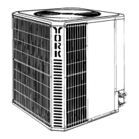
FIGURE
1
– OUTDOOR UNIT LOCA
TION
18”
SER
VICE
ACCESS CLEARANCE
60”
10” CLEARANCE
COIL AREA
WEA
THERPROOF
DISCONNECT
SWITCH
THERMOSTAT
T
O FURNACE OR AR HANDLER
TERMINAL BLOCK
NEC CLASS 1 WIRING
NEC CLASS 2 WIRING
T
O INDOOR COIL
SEAL OPENING(S) WITH PERMAGUM
OR EQUIV
ALENT
CONTROL ACCESS P
ANEL
NOTE: ALL OUTDOOR WIRING MUST
BE WEA
THERPROOF
INDOOR UNITS
Install
the indoor coil in the furnace or air handler accord
-
ing
to the installation instructions packed with each com
-
ponent.
REFRIGERANT LINES
The
following steps are very important when setting up a
refrigerant
system and need to be
followed completely to
ensure
that a strong, flexible and leak tight system is ob
-
tained.
The
installation of the copper refrigerant tubing must
be
done
with care to obtain reliable, trouble–free operation.
1. Selecting
of proper refrigerant tubing grade and
size.
2. Refrigerant
line routing, cutting and fitting.
3.
Proper preparation of joint connections.
4. Reassembling, cleaning and brazing the joint con-
nections.
5. Insulating
the vapor line.
6. Connecting
the
refrigerant lines to the indoor coil and
outdoor
unit.
7.
Pressure leak test all joints.
8.
Evacuate refrigerant lines and indoor coil.
9. Charging refrigeration system (if the line length is
other
than 15 feet.) See T
able 2.
Table 2 – Refrigerant Line Charges
Liquid
OD
V
apor OD
R–22 Charge, OZ/FT
3/8” 5/8” 0.66
3/8” 3/4” 0.68
3/8” 7/8” 0.70
3/8” 1–1/8” 0.76
1/2” 1–1/8” 1.26
Use
only ACR
grade copper tubing and keep ends sealed
until
joints are made.
The
correct diameters of the refrigerant lines are listed on
the
unit nameplate.
For best performance, select routing of refrigerant lines
for
minimum distance and fewest number of bends.
Determine the path that the refrigerant lines will follow
.
Starting
at either the indoor coil or the outdoor unit refrig
-
erant line connections, carefully measure, cut de–burr
and
fit
copper refrigerant lines along the path previously
determined.
NOTE:
If it is necessary for bends to be formed in the
vapor
line, the radius should
not be less than 12
inches.
Cut
ends of the copper tubing square.
Remove all burrs from tubing with a reamer, file or de–
burring
tool.
Slope tubing towards the outdoor unit.
When
the indoor coil is above the outdoor unit the vapor
line
should be sloped toward the outdoor unit with a fall
of
least
1/4 inch per 5 FT
.
When the outdoor unit is above the indoor coil the hori-
zontal
runs should be sloped toward the outdoor unit
as
described
above.
 Loading...