6
Unitary Products Group
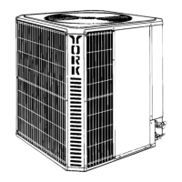
FIGURE
3
– OUTDOOR UNIT CONTROL BOX (036, 048 & 060 MODELS)
GROUND
LUG
REVERSIBLE
HIGH VOL
T
AGE CONDUIT PLA
TE
LOW VOL
T
AGE BOX
“FINGERED”
BUSHING
F
AN MOT
OR
PLUG
CONTACTOR
F
AN CAP
ACITOR
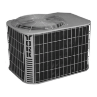
FIGURE
4
– OUTDOOR UNIT CONTROL BOX (076 & 090 MODELS)
CONTACTOR
1
LOW VOL
T
AGE BOX
“FINGERED”
BUSHING
GROUND LUG
ADJUST
ABLE
HIGH VOL
T
AGE CONDUIT PLA
TE
F
AN MOT
OR
PLUG
F
AN CAP
ACITOR
POWER WIRING
CONNECTIONS
TRANSFORMER
CONTACT
OR 2
(090 ONL
Y)
LOW VOLTAGE
Control
wiring may vary
, depending upon the type of
ther
-
mostat,
furnace or air handler being connected.
Low voltage wiring diagrams can be found with the fur-
nace or air conditioning blower package installation in-
structions.
Pig–tail connector wires are provided from the low volt-
age
pull–in coil
on the contractor to a section of the con
-
trol
box. A “fingered” bushing is provided in the low volt
-
age knockout hole. If 1/2” conduit is used for the low
voltage
wiring, the bushing is to be removed.
1. Route the low voltage cable through the fingered
bushing
i
n t
h
e l
o
w v
oltag
e j
unctio
n b
ox
. S
e
e F
igur
e 3
or
4
.
2. Using wire nuts, connect the low voltage wiring as
shown
in Figure 5, 6 or 7.
3. A minimum of 18 AWG wire gauge for total lengths
not exceeding 130 feet must be used in connecting
the low voltage control wiring between the outdoor
unit,
furnace and thermostat. For longer low voltage
control
wiring lengths, consult the N.E.C.
Connect thermostat and control package wiring as
shown
in Figure 5–7 and per the instructions packed
with
those
pieces.
 Loading...