TABLE OF CONTENTS
Unit Cooling Capacities & Power Requirements..................3
System Cooling Capacities & Power Requirements............4
Field Wiring...........................................................................6
Suction Line Data .................................................................7
Liquid Line Data....................................................................7
Refrigerant-22 Line Charge..................................................7
Sequence Of Operation........................................................7
Guide Specification ..............................................................9
Description........................................................................... 1
Features............................................................................... 1
ARI Ratings.......................................................................... 2
Unit Application Data ........................................................... 2
Physical Data....................................................................... 2
Electrical Data...................................................................... 2
Field-Installed Accessories .................................................. 2
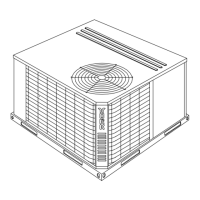
Unit Dimensions & Clearances............................................ 3
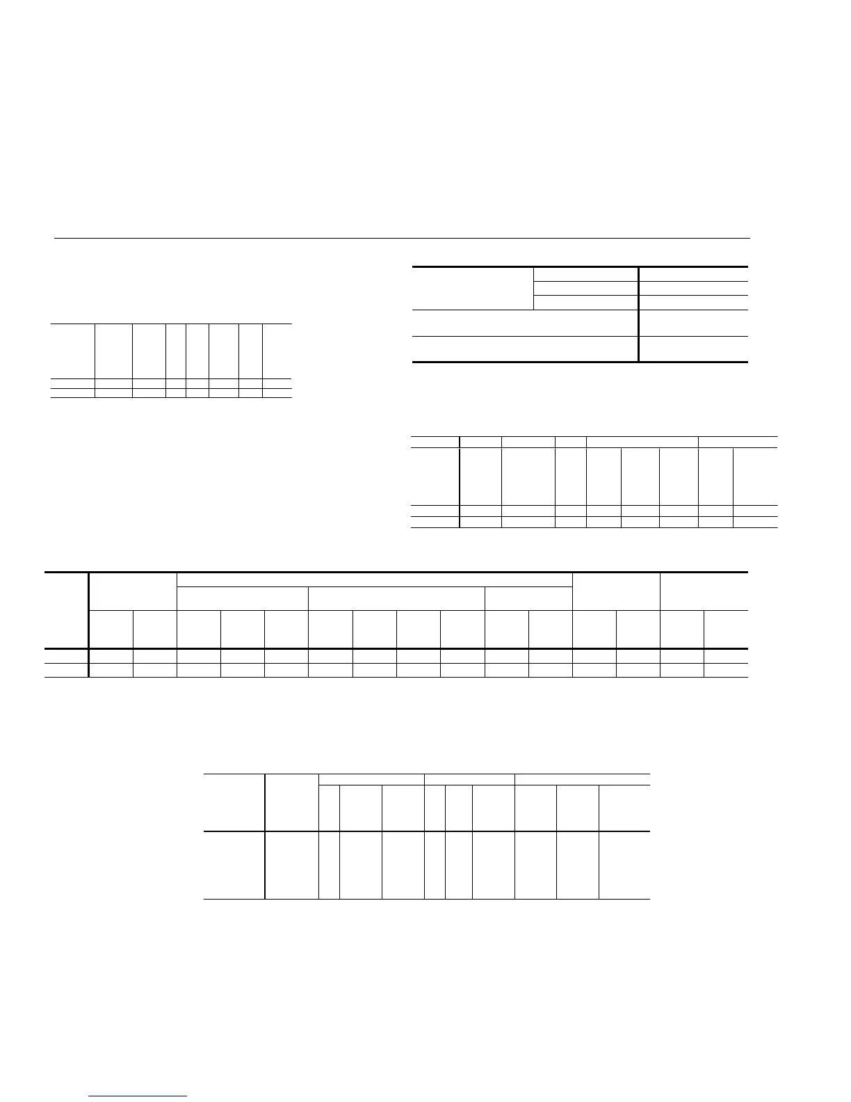
UNIT APPLICATION DATA
Voltage Variation
1
Min. / Max.
208/230-3-60 187 / 252
460-3-60 432 / 504
575-3-60 540 / 630
Ambient Air on Condenser Coil
Min. / Max.
35°F
2
/ 115°F
Ambient Air on Condenser Coil
Min. / Max. with Head Pressure Control
0 - 115°F
1 Utilization range “A” in accordance with ARI Standard 110.
2. The minimum allowed ambient temperature for mechanical cooling without the head pres-
sure control accessory installed must be raised if the indoor air flow is less than the mini-
mum value given in the capacity tables.
PHYSICAL DATA
Compressor Condenser Fan Motor Unit
Model
Unit Power
Supply
Qty RLA LRA Qty HP FLA
Minimum
Circuit
Ampacity
(Amps)
Maximum
Fuse
Size
1
(Amps)
Minimum
Disconnect
Size
2
(Amps)
H3CE180A25 208/230/3/60 2 26.4 189 2 1 5.0 69.4 90 100
H3CE180A46 460/3/60 2 13.9 94 2 1 2.6 36.5 50 60
H3CE180A58 575/3/60 2 10.1 74 2 1 2.0 26.7 35 30
H3CE240A25 208/230/3/60 2 37.4 278 2 1 5.0 94.2 125 100
H3CE240A46 460/3/60 2 18.4 127 2 1 2.6 46.6 60 60
H3CE240A58 575/3/60 2 15.2 100 2 1 2.0 38.2 50 60
1. Dual element, time delay type.
2. Refer to NEC/NFPA No. 70, Articles 440-11,12 for information on minimum disconnect sizing.
3. The 208-230 V compressors and motors use a single tap for the entire range of voltages.
The 208/230 V to 24 V transformers have different taps for 208 and 230 V.
ARI RATINGS
1
Condensing
Unit
Air
Handler
Net
Capacity
MBH (1)
EER
(1)
IPLV
(1)
Cond.
Unit
Sound
dB (2)
Rated
Air
Flow
CFM
Rated
Ext.
Static
Press
IN WC
H3CE180 K1EU180 172 9.0 11.4 91.0 6000 0.35
H3CE240 L3EU240 234 8.8 11.0 89.0 7000 0.40
1. Rated in accordance with ARI 360.
2. Rated in accordance with ARI 370.
3. All ratings were determined with 25 feet of interconnecting tubing and with the
air handler in the horizontal position.
For the 180, a 5/8 inch liquid line and an insulated 1-5/8 suction line were used.
For the 240, a 7/8 inch liquid line and an insulated 2-1/8 suction line were used.
4. For 208 V operation, derate the 180 and 240 capacity 1% and add 2 dB
to H3CE240 sound rating.
FIELD-INSTALLED ACCESSORIES
• 0°F LOW AMBIENT - A single phase condenser fan motor and head pressure control to reduce its speed maintain stable system
operation at ambient temperatures down to 0°F.
• Coil Guard - A decorative coil guard provides an additional level of protection for the condenser coils.
ELECTRICAL DATA
Model
Size
(Mbh)
Compressor
1
Condenser
Unit Weight
(Lbs.)
Charge,
(Refrigerant-22)
Lbs.-Oz.
24" Fan (Propeller) Fan Motor
2
Coil
Rating
(Tons)
Cap.
(Stg’s.)
Qty.
Blades/
Pitch
(Deg.)
Nom.
CFM
Qty. HP RPM Rotation
Fins
per
inch
Rows
Deep
Ship. Oper. Holding
3
Oper.4
180 15 2 2 3/32 10,800 2 1 1100 CCWLE 20 2 920 930 2 - 0 24 - 12
240 20 2 2 3/32 11,300 2 1 1100 CCWLE 20 2 970 990 2 - 0 32 - 13
1
Compressor set consists of two Copeland scroll compressors manifolded into a single refrigerant circuit.
2
The ball bearing, 48 frame, single phase condenser fan motor have internal protection are directly connected to the condenser fans.
Motor rotation is counterclockwise when viewing the lead end,which is opposite the shaft end.
3
Holding charge is the amount in the unit as shipped from the factory.
4
Operating refrigerant charge is for the condensing unit and the matching York air handler, but does not include the charge in the interconnecting piping.
See the Refrigerant Line Charge Table to determine the additional refrigerant charge required for interconnecting piping.
Evaporator
Condensing
Unit
Air
Handler
Single
Compressor
Net Capacity
MBH
1
EER
Air Flow
CFM
Entering
Dry Bulb
F
Entering
Wet Bulb
F
Rated
Ext.
Static
Press
IN WC
Condenser
Entering
Dry Bulb F
H3CE180 K1EU180 107 11.6 6000 80 67 0.35 80
H3CE240 L3EU240 127 11.0 7000 80 67 0.40 80
1. For 208 V operation, derate capacity 1%.
PART LOAD CAPACITY & EFFICIENCY
550.23-TG3Y
2 Unitary Products Group
 Loading...