8
ENGLISH
3
2
1
4
C
A
B
5
6
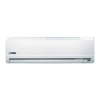
MODEL 12
PARTS INSTALLATION
Cautions on remote controller installation
otrellortnocetomerehtetarepo,noitallatsnierofeB•
determine its location in a reception range.
• Keep the remote controller at least 1 m apart from the
nearest TV set or stereo equipment.
•
Do not install the remote controller in a place exposed to
direct sunlight or close to a heating source, such as a stove.
•
Note that the positive and negative poles are right positions
when loading batteries.
The air-conditioner can be connected only to a supply
with system impedance no more than 0.26 ohm. In case
necessary please consult your supply authority for system
impedance information.
NOTE: At least two of A, B, C aspect are free from blocking.
15cm or more
12cm or more
12cm or more
Air lter
Remote controller
Mounting screw B
ST2.9x10-C-H
Remote controller
holder
Loop the
connective
cable.
30 cm or more
Air blowing
direction
60 cm or more
200 cm or more
30 cm or more
eromromc
06
INDOOR UNIT
INSTALLATION PROCEDURE
.....
...
......
....
...
.
.
.....
..
..
...
......
..
..
.
....
..
.
....
...
...
....
...
.....
...
...
...
..
..
.....
.
.
....
..
.
.....
..
.
...
..
.
..
.
..
Fixing
• Place the installation guide pattern on the designated
installation place and mark the hole position.
• Drill a hole and mount installation plate.
• After determining the pipe
elohehtllirdnoitisopeloh
tnalsdrawnwodthgilsata
towards the outdoor side.
ø65 mm
Outdoor
Indoor
Note: When installing
the refrigerant pipes from
others side. A hole must
be place to allow fall
towards the outdoor unit.
•
Make6 mm 4-6holes, in the wall at the four corners of mouting
plate (bracket) then insert appropriate mounting devices.
•
Install the mounting plate using 4-6 pieces of mounting screw
securely at four corners and tighten the screw completely.
Do not over tighten the screws and deform the back plate.
Name of part
Q’ty
Installation plate
Mounting screw ST3.9x25-C-H
Clip anchor
Remote controller
Remote controller holder
Seal
Drain elbow
J435.indd 8 1/22/08 11:13:53 AM
MODEL 18
Indoor unit outline
120mm or more
to wall
120mm or more
to wall
Left refrigerant
pipe hole 65
R ight re frigera nt
pipe hole 65
Ins tallation plate
280
815
150mm or more to ceiling
50
50
50
42
906
49
90
55
50
65mm
Rear-right pipe
hole
120mm or more to the wall
120mm or more to the wall
Indoor unit outline
Installation plate
150mm or more
to the ceiling
Rear-left pipe
hole 65mm
Liquid side
ø 6.35 (12000-21000 Btu/h)
Parts you
must
purchase
ø 9.53 (24000-36000 Btu/h)
Gas side
ø 12.7 (12000-21000 Btu/h)
ø 16 (24000-36000 Btu/h)
Part No.
1
2
3
4
5
6
7
8
Refrigerant
pipe
1
8
8
1
1
1
1