5715184-BIM-A-0519
8 Johnson Controls Ducted Systems
DOWNFLOW APPLICATION
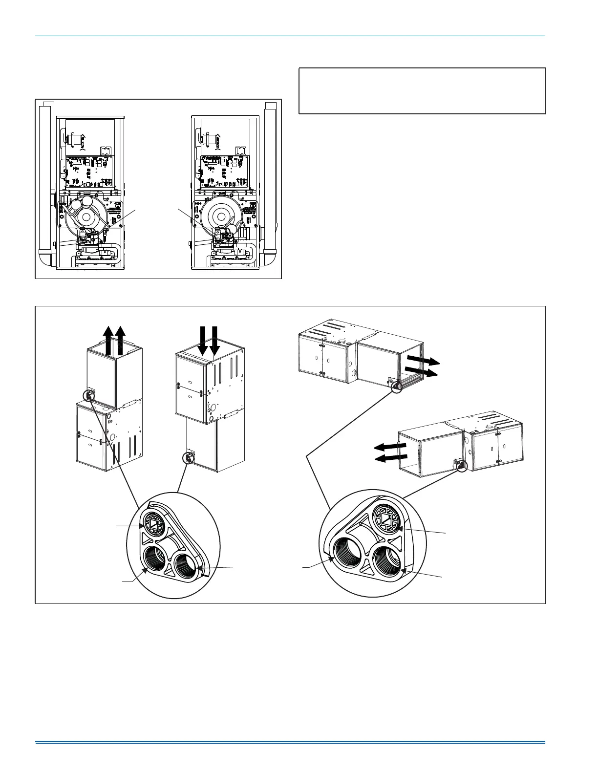
Furnace is shipped in downflow configuration. It may be necessary to
rotate the vent blower 180° left so that the vent pipe passes through the
side of the furnace casing. See Figure 7.
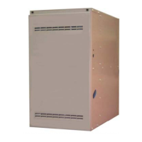
COIL INSTALLATION
The indoor coil must be mounted on the supply side of the furnace as
shown in Figure 8. Refer to the Installation Instructions provided with
each indoor coil.
FIGURE 7: Downflow Venting
/()76,'(9(17
5,*+76,'(9(17
5RWDWHYHQW
EORZHU
HLWKHUZD\
$
IMPORTANT: On all installations without a coil, a removable
access panel is recommended in the outlet duct such that smoke or
reflected light would be observable inside the casing to indicate the
presence of leaks in the heat exchanger. This access cover shall be
attached in such a manner as to prevent leaks.
FIGURE 8: Furnace and Coil Attachment
$
127(
9HULI\WKDWDOOGUDLQV
DUHWUDSSHGRUSOXJJHG
83)/2:
$33/,&$7,21
'2:1)/2:
$33/,&$7,21
35,0$5<'5$,1
75$3&211(&7,21
6(&21'$5<'5$,1
75$3&211(&7,21
'5$,13/8*
)25+25,=217$/
6(&21'$5<'5$,1
35,0$5<'5$,1
75$3&211(&7,21
&2,/
&2,/
5,*+7)/2:
$33/,&$7,21
/()7)/2:
$33/,&$7,21
&2,/
&2,/
'5$,13/8*
)259(57,&$/
6(&21'$5<'5$,1
)851$&(
)851$&(
)851$&(
)851$&(