YORK INTERNATIONAL
97
FORM 150.62-NM2
KEYPAD
The operator keypad is connected to the microboard by
a ribbon cable, which is connected to J2 on the
microboard.
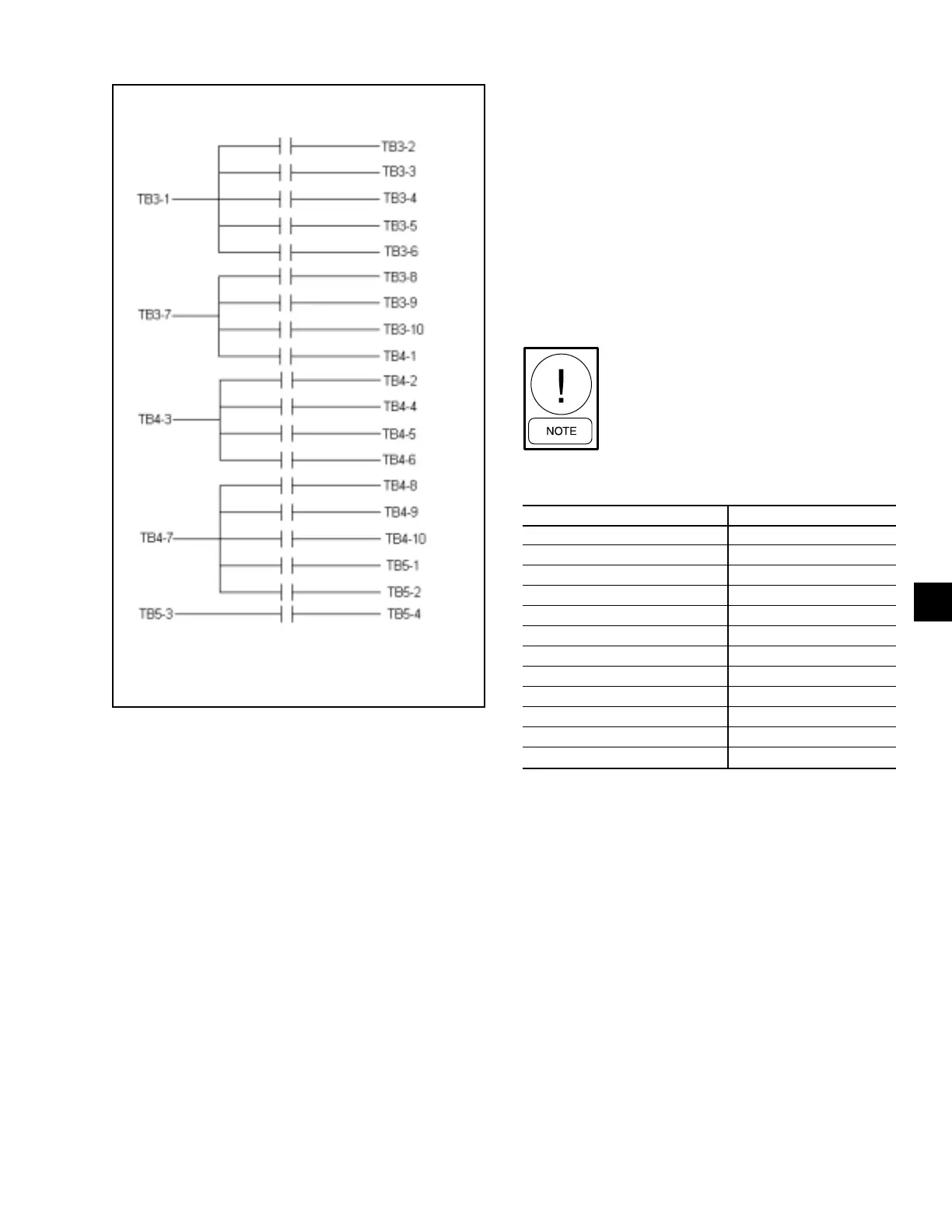
The integrity of a specific “button” on the keypad can be
verified by doing a continuity check across two specific
points (or pins), that represent one of twelve “buttons” on
the keypad.
Table 46 lists the key/pin assignments for the keypad.
Power to the microboard must be turned off, and
the ribbon cable disconnected from the microboard
prior to conducting the tests, or component dam-
age may result.
After the ribbon cable is disconnected from microboard,
ohmmeter leads are connected to the pins representing
the specific “button” to be tested. After connecting the
meter leads, the “button” being checked is pressed and
a reading of zero ohms should be observed. After releas-
ing the “button”, the resistance value should be infinite
(open circuit).
Pin 1 is usually identified by a stripe on
the ribbon cable.
FIG. 9 – MICROBOARD RELAY CONTACT
ARCHITECTURE
LD03842
TABLE 46 – KEYPAD PIN ASSIGNMENT MATRIX
KEYPAD PIN CONNECTIONS
STATUS 1 TO 5
OPER DATA 1 TO 7
PRINT 1 TO 6
HISTORY 1 TO 8
UP ARROW 2 TO 5
DOWN ARROW 2 TO 7
ENTER/ADV 2 TO 6
COOLING SETPOINTS 2 TO 8
SCHEDULE/ADVANCE DAY 3 TO 5
PROGRAM 3 TO 7
OPTIONS 3 TO 6
CLOCK 3 TO 8
3

 Loading...


