035-14370-000 650.75-N4U
Unitary Products Group 15
NOTE.
Some electronic thermostats do not have adjustable
heat anticipators. They may have other type cycle rate
adjustments. Follow the thermostat manufacturer's instruc-
tions.
The 24-volt, 40 VA transformer is sized for the furnace com-
ponents only, and should not be connected to power auxiliary
devices such as humidifiers, air cleaners, etc. The trans-
former may provide power for an air conditioning unit contac-
tor.
COMBUSTION AIR AND VENT SYSTEM
1. Two-pipe with a sealed combustion intake/vent system
usin
outdoor combustion air.
2. Sin
le pipe vent system usin
combustion air from the
area surroundin
the furnace.
3. Two-pipe intake/vent system usin
combustion air from a
ventilated attic space and a vent pipe to the outside.
Be sure to follow the appropriate venting section details,
related information and limitations for your type of installation.
METHOD ONE: TWO PIPE SEALED COMBUSTION
AIR & VENT SYSTEM
COMBUSTION AIR INTAKE/VENT CONNECTIONS
This type installation requires outdoor combustion air. Two
separate, properly-sized pipes must be used. One bringing
air from the outdoors to the furnace combustion air intake col-
lar on the burner box, and a second pipe from the furnace
vent connection (top right of unit) back to the outdoors. Refer
to Figure 15 and Figure 16.
The intake/vent should be located either through the wall
(horizontal or side vent) or through the roof (vertical vent).
Care should be taken to locate side vented systems where
trees or shrubs will not block or restrict supply air from enter-
ing or combustion products from leaving the terminal.
Also, the terminal assembly should be located as far as pos-
sible from a swimming pool or a location where swimming
pool chemicals might be stored. Be sure the terminal assem-
bly follows the outdoor clearances listed in Table 3 for U.S.
installations: In Canada, refer to CAN/CGA-B149.1 or.2
This furnace is certified to be installed with one of
three possible intake/vent configurations.
Furnace Intake / Vent Connection Size (All Models)
40 - 100 MBH 120 - 140 MBH
Intake 2” 3"
Vent 2”
2"
1
1.
Vent must be increased to 3" on this model.
Note 1: Any vent pipe size change must be made out-
side furnace casing in a vertical pipe section
to allow proper drainage of condensate.
Note 2: An offset using two 45 degree elbows will be
required for plenum clearance when the vent
is increased to 3”.
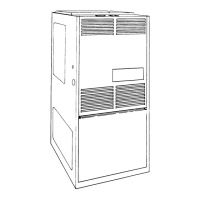
FIGURE 15 : UPFLOW AIR INTAKE/VENT LOCATIONS
(MODELS P*UR / FG9-UP /G9T-UP)
FIGURE 16 : DOWNFLOW / HORIZONTAL AIR
INTAKE/VENT LOCATIONS (MODELS
P*DH / FG9-DH /G9T-DH)
M
P
C
1
3
2
O F F
O N
C O M B U S T IO N A IR P IP E
PASSES THR O UG H TO P PANEL
CONNECTS TO COLLAR
O N T O P O F B U R N E R B O X
VENT PIPE
CEM ENTS
IN T O S O C K E T J U S T
UNDER TOP PANEL
YWRG
C
COOL
HEAT
PARK
PARK
LINE
XFMR
EAC
HUM
CIR
LINE
XFMR
EAC
HUM
VENT PIPE PASSES
THRO UG H TO P PANEL
COM BUSTION AIR PIPE
CONNECTS TO COLLAR
ON BOTTOM OF BURNE
BO X
OPTIONAL
L E F T S ID E
COM BUSTION AIR
PIPE RO UTIN G
 Loading...