035-14370-000 650.75-N4U
Unitary Products Group 9
RETURN DUCT CONNECTION
Return air may enter the furnace through the side(s) or bot-
tom depending on the type of application.
Return air may
not be connected into the rear panel of the unit.
See the
specific type application installation for details. Be sure to see
the Filters section of this instruction.
UPFLOW FILTER INSTALLATION
All applications require the use of a filter. A high velocity filter
and retainer are provided for field installation.
Internal Installation
1. Select desired filter position (left/ri
ht side, or bottom).
Remove the correspondin
cabinet cut-outs per instruc-
tions provided.
2. Install snap-in retainer clips into the correspondin
slots
from the outside rear of the cabinet (Refer to Fi
ure 3.)
To prevent cabinet air leaks, install snap-in plu
s (pro-
vided) into the unused slots at the outside rear of the
cabinet.
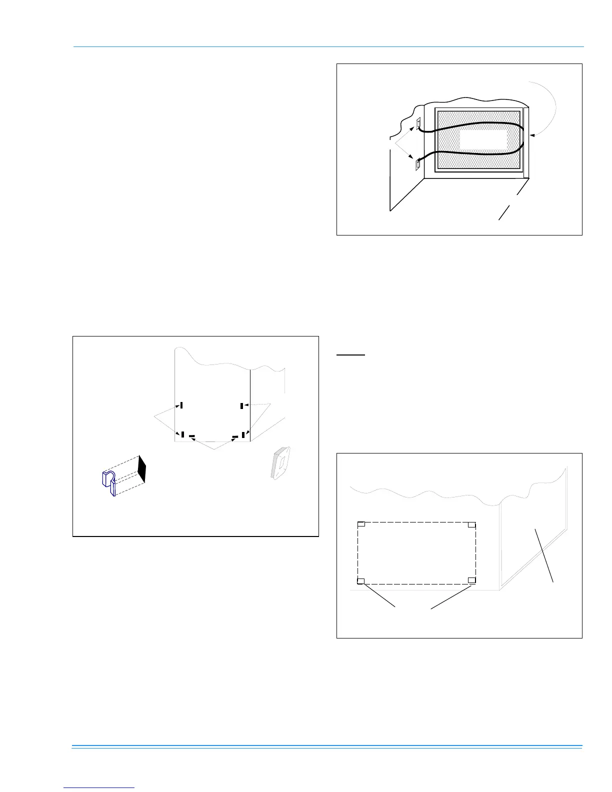
3. Install the wire retainer inside the cabinet. Insert the
open ends of the wire retainer into the clip loops at the
rear of the blower compartment. The retainer wire should
pivot freely like a hin
e, on the clips at the rear of the
cabinet. (Refer to Fi
ure 4.)
4. Install the filter(s) provided. Cut filter if necessary to
match air openin
in cabinet. Filter should extend
beyond openin
ed
e as much as possible to prevent air
from bypassin
the filter. DO NOT remove stiffenin
rods
from inside the filter. Shorten the rods, if necessary, to
match final filter size.
5. Position the filter between the wire retainer and the cabi-
net wall (or floor) so it completely covers the cabinet air
opening and secure the filter in place at the front of the
cabinet by fastening the closed (looped) end of the
retainer wire under the flanged edge of the cabinet.
When properly installed the filter should fit flush with all
four sides of the cabinet wall.
NOTE:
Air velocity through throw-away type filters may not
exceed 300 feet per minute. All velocities over this require the
use of high velocity filters.
Side Return - External Filter
Locate and knock out the square corner locators. These indi-
cate the size of the cutout to be made in the furnace side
panel (Refer to Figure 5).
Install the side filter rack following the instructions provided
with that accessory. If a filter(s) is provided at another loca-
tion in the return air system, the ductwork may be directly
attached to the furnace side panel.
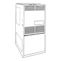
FIGURE 3 : FURNACE FILTER SLOT LOCATIONS
FURNACE
(REAR CABINET)
RIGHT
SIDE
SLOTS
LEFT
SIDE
SLOTS
BOTTOM SLOTS
CABINET
SLOT
FILTER SUPPORT
CLIPS (PROVIDED)
PLUG UNUSED
CABINET SLOTS
WITH PLUGS
(PROVIDED)
FIGURE 4 : SIDE FILTER RETAINER PLACEMENT
FIGURE 5 : SIDE RETURN CUTOUT MARKINGS
RIGHT SIDE
INSTALLATION
SHOWN
CLIPS
FILTER
(PROVIDED
POSITION WIRE RETAINER
(PROVIDED) UNDER FLANGE
FURNACE
FRONT
FR O N T O
FU R N AC E
CORNER
MARKINGS
 Loading...