EasyManua.ls Logo

York R410A - User Manual

York R410A
28 pages
Print Icon
To Next Page IconTo Next Page
Loading...
No. 0150520007
Read this manual before installation and operation
Make sure that it is well kept for later reference
Floor Ceiling R410A 50Hz
USER'S MANUAL
YIFFZC025BAEFA
YIFFZC030BAEFA
YIFFZC036BAEFA
YIFFZC036BANFA
YIFFZC040BAEFB
YIFFZC040BANFA
Question and Answer IconNeed help?

Do you have a question about the York R410A and is the answer not in the manual?

Summary

Cautions

Safety Instructions and Warnings

Crucial safety guidelines for installation, operation, and maintenance.

Safety Precautions

Critical Warnings

Critical safety warnings regarding electrical connections, operation, and installation.

Danger Warnings

Severe danger warnings related to improper installation, repairs, and handling.

General Operation Warnings

General warnings for safe operation, including ventilation and avoiding obstructions.

Troubleshooting

Air Conditioner Wont Start

Checks for issues when the air conditioner fails to power on.

Poor Cooling;Heating Performance

Diagnostic steps for inadequate cooling or heating performance.

Poor Cooling Diagnosis

Specific checks for issues related to poor cooling performance.

Error Code Diagnostics

Model YIFFXC025 BAEFA Error Codes

Lists error codes and possible reasons for specific air conditioner models.

Model YIFFXC040 BAEFB Error Codes

Lists error codes and possible reasons for the YIFFXC040BAEFB model.

YIFFYC036 BANFA;YIFFYC040 BANFA Error Codes

Lists error codes and possible reasons for specific air conditioner models.

YIFFXC040 BAEFB Error Codes (Continued)

Lists error codes and possible reasons for the YIFFXC040BAEFB model.

Installation Procedure

Installation Precautions

Important precautions to ensure safe and correct installation by professionals.

Installation Warnings

Warnings for professional installation regarding water leaks, shock, and fire hazards.

Refrigerant Piping Procedures

Procedures and guidelines for connecting refrigerant piping between indoor and outdoor units.

Refrigerant Piping Precautions

Essential precautions to prevent damage and ensure safe refrigerant piping installation.

Air Discharging and Tightness Test

Procedure for performing an air tightness test using nitrogen gas.

Indoor Unit Vacuumizing

Steps for vacuumizing the system after air tightness testing.

Refrigerant Charging Amount

Instructions on calculating and charging additional refrigerant based on pipe length.

Electrical Wiring Connections

Detailed instructions for electrical wiring connections to the unit terminals.

Test Run

Overview

This document serves as the User's Manual for YORK Floor Ceiling R410A 50Hz air conditioners, specifically covering models YIFFZC025BAEFA, YIFFZC030BAEFA, YIFFZC036BAEFA, YIFFZC036BANFA, YIFFZC040BAEFB, and YIFFZC040BANFA. It provides essential information for installation, operation, and maintenance, emphasizing safety precautions and troubleshooting.

Function Description

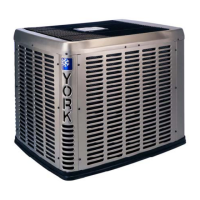
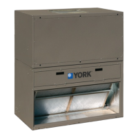
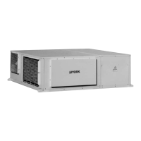
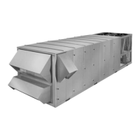
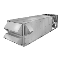
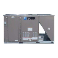
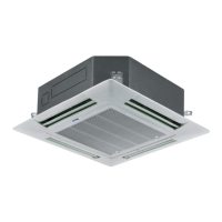
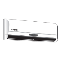
The YORK Floor Ceiling R410A 50Hz air conditioner is designed for cooling, dehumidifying, and ventilation in ordinary dwellings. It operates using refrigerants that require specialized waste disposal. The unit features an indoor and outdoor component, with the indoor unit having an operating control panel, emergency switch, various indicator lamps (Power, Operation, Timer, Compressor), and a remote receiver. The outdoor unit includes a compressor and air inlet/outlet.

Important Technical Specifications

Refrigerant Circuit: The refrigerating circuit is leak-proof. Power Supply Disconnection: For all models, an all-pole disconnection method must be applied in the power supply, incorporated into the fixed wiring. The breaker should be an all-pole switch with a contact distance of no less than 3 mm. Wiring: Only copper wire with a local authentication certificate should be used. Power supply connects from the outdoor side, with connecting and power cables being self-provided. Temperature and Humidity Range (Cooling):

  • Indoor Temperature: Max DB/WB 32/23 °C, Min DB/WB 18/14 °C
  • Outdoor Temperature: Max DB/WB 43/26 °C, Min DB/WB 18/- °C Fuse: If the fuse on the PC board is broken, it should be replaced with a type T3.15A/250VAC. Connection Pipe Requirement (Diameter and Length):
  • YIFFYC025BAEFA: Liquid side Ø9.52 mm, Gas side Ø15.88mm; Max length 30 m, Max height 10m.
  • YIFFYC030BAEFA, YIFFYC036BAEFA, YIFFYC036BANFA: Liquid side Ø9.52 mm, Gas side Ø19.05mm; Max length 30 m, Max height 10m (for 030) / 15m (for 036).
  • YIFFYC040BAEFB, YIFFYC040BANFA: Liquid side Ø9.52 mm, Gas side Ø19.05mm; Max length 50 m, Max height 20m. Refrigerant Charging: For connecting pipes less than 7.5m, no additional refrigerant is needed. If exceeding 7.5m, charge (L-7.5) x 50 (g) of additional refrigerant per meter, only in COOLING operation and in liquid condition. Fastening Torque for Pipes:
  • Liquid pipe 6.35mm: 14.2-17.2N·m
  • Liquid pipe 9.52mm: 32.7-39.9N·m
  • Gas pipe 12.7mm: 49.5-60.3N·m
  • Gas pipe 15.88mm: 61.8-75.4N·m
  • Gas pipe 19.05mm: 97.2-118.6N·m Power Supply and Interconnecting Wires (20m length, <2% voltage drop):
  • YIFFYC025BAEFA: 1PH, Switch breaker 30A, Overcurrent protector 18A, Wire size 4.0mm², Earth leakage breaker 30A/30mA.
  • YIFFYC030BAEFA, YIFFYC036BAEFA, YIFFYC040BAEFB: 1PH, Switch breaker 40A, Overcurrent protector 20A/24A/28A, Wire size 5.3mm², Earth leakage breaker 40A/30mA.
  • YIFFYC036BANFA, YIFFYC040BANFA: 3PH, Switch breaker 30A, Overcurrent protector 8A/10A, Wire size 2.5mm², Earth leakage breaker 30A/30mA.

Usage Features

  • Operation Control Panel: The indoor unit features an operating control panel with indicator lamps for Power, Operation, Timer, and Compressor status.
  • Emergency Switch: An emergency switch is provided for immediate control.
  • Remote Receiver: The unit can be controlled via a remote receiver. For wired control units, the wired controller is used instead.
  • Automatic Restart: The unit has an automatic restart system that activates after power stoppage.
  • Swing Motor Test: When the indoor unit is turned on, the PCB tests the swing motor, and then the fan motor starts up after a few seconds.
  • Anti-condensation: In cooling mode, the flaps automatically swing to a fixed position to prevent condensation.
  • 3-Minute Delay Protection: After stopping, the unit will not resume cooling, dry, or heating operation for 3 minutes due to a built-in delay protection circuit.
  • Dry Mode Fan Speed: In dry mode, the unit will repeatedly and automatically reduce fan speed if the room temperature is too low.
  • Indoor Fan Operation (Heating): In heating operation, the indoor fan continues running until the indoor unit cools down after the unit is stopped.

Maintenance Features

  • Air Filter Cleaning: Filters can be easily removed from the intake grill, cleaned with a vacuum cleaner or by washing, and then re-attached.
  • Regular Inspection: For extended use, regular inspection by authorized service personnel is recommended due to potential dirt accumulation inside the unit.
  • Cleaning Precautions: When cleaning the unit's body, avoid water hotter than 40°C, harsh abrasive cleansers, volatile agents (benzene, thinner), liquid insecticides, or hairsprays.
  • Drying Internal Parts: If the unit is shut down for a month or more, operate it in Fan mode continuously for about half a day to thoroughly dry internal parts.
  • Base Check: After long-term use, the unit's base should be checked for damage to prevent accidents.
  • Troubleshooting Guide: The manual includes a comprehensive troubleshooting guide for common issues like the unit not starting, poor cooling/heating, and various error codes indicated by LED flashes on the receiver board.
  • Error Code Diagnosis: Detailed tables are provided for diagnosing issues based on LED flash times, identifying malfunctions such as sensor errors, compressor overcurrent, communication problems, and drain system malfunctions.
  • Test Run Procedure: A test run procedure is outlined for both indoor and outdoor units, including checks for remote control function, lamp indicators, louvers, drain, abnormal noise/vibration, and gas leakage. For heat pump models, it's crucial to energize the crankcase heater for over 12 hours before the test run.

York R410A Specifications

General IconGeneral
BrandYork
ModelR410A
CategoryAir Conditioner
LanguageEnglish

Related product manuals