Do you have a question about the York SUNLINE 2000 B1CH180 and is the answer not in the manual?
Identifies specific unit models B1CH180 & 240.
Critical safety precautions for installation and servicing.
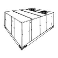
Provides basic information about the YORK BCH heat pump units.
Procedure for inspecting the unit for transit damage.
Lists supporting documentation for unit operation and service.
Details ETL and CGA design certifications for the unit.
Specifies national and local code requirements for installation.
Provides recommendations for selecting a suitable installation site.
Instructions for safely moving and lifting the unit.
Required clearances for proper unit operation and servicing.
Guidelines for designing and connecting ductwork systems.
Installation steps for the fixed outdoor air intake damper.
Plumbing requirements for the condensate drain line.
Information on compressor mounting and factory settings.
Details on filter types, installation, and maintenance.
Identifies removable panels for accessing unit components.
Guidelines for locating and wiring the room thermostat.
Instructions for field wiring electrical connections.
Installation details for optional electric heater accessories.
Instructions for installing economizer or motorized damper rain hoods.
Procedure for adjusting the enthalpy set point controller.
Details on the power exhaust and barometric relief damper option.
Diagrams and guidelines for low voltage thermostat wiring.
Field wiring instructions for unit power supply connections.
Description of the unit's air-cooled cooling system.
Steps for initial compressor startup before full service.
Details how the unit operates in cooling mode.
Explains operation with enthalpy sensors and power exhaust.
Operation of units with motorized outdoor air dampers.
Describes how the unit operates in heating mode.
Table and guidance for setting the heat anticipator.
Procedure for measuring and verifying supply air CFM.
Explains the automatic defrost control sequence.
Conditions that trigger system lockout and reset procedures.
Final steps to obtain owner acceptance of the system.
Routine inspection and cleaning tasks for the unit.
Procedure for cleaning the outdoor condenser coil.
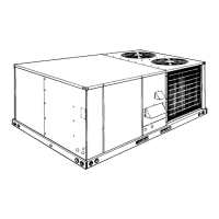
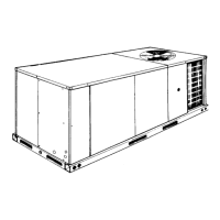
This document describes the installation and maintenance of Sunline 2000™ Single Package Heat Pumps from York, specifically models B1CH180 and B1CH240, which have an 8.5 - 8.8 EER (Energy Efficiency Ratio). These units are designed for outdoor installation, either on a rooftop or a slab, and can be equipped with factory-installed electric heaters for both cooling and heating applications.
The York Sunline 2000™ heat pumps provide both cooling and heating for commercial or residential spaces. They are self-contained units, meaning all major components like compressors, coils, and blowers are housed within a single cabinet. The units are factory-charged with Refrigerant-22 and feature hermetically sealed, internally sprung, and base-mounted compressors with rubber-insulated hold-down bolts. These compressors include inherent (internal) protection that will shut down the compressor if an abnormal temperature rise occurs.
For cooling, the system operates in stages. When the room thermostat calls for "first-stage" cooling, the low voltage control circuit energizes compressor #1, outdoor fan motors (if ambient temperature is above 60°F), and the supply air blower motor. For "second-stage" cooling, compressor #2 is also energized. The reversing valve is energized through the "Y1" circuit in cooling mode. A suction line freezestat cuts off compressors if the suction line temperature drops below 26°F.
For heating, the system also operates in stages. "First-stage" heating energizes the compressors, outdoor fan motors, and blower motor. If the compressors alone cannot meet the heating demand, "second-stage" heating activates the supplemental electric heat (if installed).
Optional economizers are available, which allow the unit to use outdoor air for cooling when conditions are favorable, improving efficiency. Single enthalpy economizers use an outdoor air sensor, while dual enthalpy economizers also incorporate a return air sensor to select the air source with the lowest enthalpy. Power exhaust options are available with economizers to manage indoor air pressure. Motorized outdoor air dampers can also be installed to control the amount of fresh air intake.
The units feature an "ambient modified" time-temperature defrost control for heating. This control automatically adjusts defrost initiation times based on outdoor temperature, shortening them above 35°F and extending them below 35°F. Defrost terminates when the liquid line sensor reaches 55°F or after 10 minutes.
The units are available in 15 Ton (B1CH180) and 20 Ton (B1CH240) nominal cooling capacities. Nominal heating capacities range from 18 KW to 72 KW, depending on the model and installed electric heat. Voltage variations are supported for 208/230-3-60, 460-3-60, and 575-3-60 systems. Supply air CFM ranges from 4500 to 7200 for 15-ton models and 6000 to 9400 for 20-ton models. Minimum/maximum wet bulb temperature of air on indoor coil is 57/72°F. Minimum/maximum dry bulb temperature of air on outdoor coil is 45/120°F. The units are equipped with 2-inch filters. Refrigerant 22 charge for System No. 1 is 20 lbs./8 oz. (15 ton) and 24 lbs./0 oz. (20 ton), and for System No. 2 is 22 lbs./8 oz. (15 ton) and 25 lbs./0 oz. (20 ton). Operating weights for basic heat pump units are 2000 lbs. (15 ton) and 2200 lbs. (20 ton), with additional weight for options like economizers (160 lbs.), power exhaust (245 lbs.), motorized dampers (150 lbs.), and electric heaters (25-40 lbs. depending on KW). The units are designed for zero clearance to combustible materials when equipped with electric heat. Minimum circuit ampacity and maximum time delay fuse sizes are provided in detailed electrical data tables, varying by model, voltage, and installed electric heat.
The units are designed for outdoor installation only, either on a level concrete slab (minimum 4 inches thick, at least 6 inches larger than the unit base rails) or a solid level roof curb/angle iron frame. Proper clearances are required around the unit for operation and servicing, with specific dimensions for front, back, left, right, and above the unit. Overhanging structures or shrubs should not obstruct the outdoor air discharge outlet. Ductwork should be designed and sized according to ACCA methods, using a closed return duct system. Flexible joints are recommended for supply and return air connections to minimize noise. A fixed outdoor air intake damper is shipped inside the return air compartment and is adjustable to provide variable amounts of outdoor air intake. Condensate drain lines must be trapped and conform to local plumbing codes. The room thermostat should be located on an inside wall, approximately 56 inches above the floor, away from drafts, sun exposure, or heat sources. Eight conductors are typically required for standard thermostats, and nine for thermostats with an "Emergency Heat" position. A fused disconnect switch, separate from other circuits, must be field-provided for the unit. The enthalpy set point for economizers can be adjusted to optimize performance based on desired conditions. The defrost control has adjustable settings (50, 80, or 110 minutes) to accommodate different humidity levels. A lockout control system protects the unit from various conditions (e.g., high discharge line temperature, high discharge pressure, low suction line temperature, low pressure cut-out) and illuminates an emergency heat light on the thermostat and an LED on the unit relay board.
Filters: Inspect monthly. Replace disposable filters or clean permanent filters as necessary. Dirty filters reduce capacity and can lead to frosted coils or safety shutdowns. Motors: Outdoor fan motors are permanently lubricated and require no maintenance. Indoor blower motors feature ball bearings that do not require periodic lubrication, but periodic lubrication can extend their life. Over-lubrication should be avoided. Annually, check motors for dust accumulation, loose/damaged/misaligned drive components, and tight mounting bolts. Outdoor Coil: Clean as often as necessary to prevent dirt accumulation on the coil surface or other air circuit parts. Use a brush, vacuum cleaner attachment, or water (with electric power disconnected). Care should be taken not to damage coil fins. Belt Drive Blower: All units have belt drive single-speed blower motors. The variable pitch pulley on the blower motor can be adjusted to obtain the desired supply air CFM. Belt tension should be checked and adjusted using a belt tension checker, especially during the first 24 hours of operation. Preliminary Operation: Before initial operation, crankcase heaters must be energized for at least four hours. Compressors should be given three false starts (energized just long enough to make a few revolutions) with 5-7 minutes delay between each start, before full-time service. This procedure should also be followed at the beginning of each cooling season. Troubleshooting: If a lockout occurs, check for dirty filters, snow accumulation, or leaf/debris blockage. The system can be reset by turning the thermostat switch to "OFF" for 10 seconds, then back to its original position. Access Panels: Removable panels provide access to all serviceable components, including the compressor compartment, electric heat compartment, side supply/return air compartments, blower compartment, main control box, filter compartment, and outdoor air compartment. Ensure all screws and panel latches are replaced and properly positioned to maintain an air-tight seal. Owner Approval: After proper functioning is confirmed, the installer should secure the owner's approval, showing them the location of disconnect switches and the thermostat, and teaching them how to operate and adjust temperature settings within system limitations.