035-14841-000 Rev. A (0701)
6 UnitaryProductsGroup
Refer to Figure 5 for location of these access panels.
THERMOSTAT
The room thermostat should be located on an inside wall
approximately 56" above the floor where it will not be subject
to drafts, sun exposure, or heat from electrical fixtures or
appliances. Follow manufacturer's instructions enclosed with
thermostat for general installation procedure. Color coded
insulated wires (#18 AWG) should be used to connect ther-
mostat to unit. See Figure 4 for wiring details.
NOTE: If the unit has an economizer, remove jumper J1
from terminals 8 and 10 on the relay board to pre-
vent simultaneous operation of the compressor and
the economizer. If you want to control the econo-
mizer on a second stage of cooling, use a thermo-
stat with two stages of cooling.
POWER AND CONTROL WIRING
Field wiring to the unit must conform to provisions of the
National Electrical Code (NEC) ANSI/NFPA 70 (in USA), cur-
rent Canadian Electric Code (CEC) C22.1 (in Canada) and/or
local ordinances. The unit must be electrically grounded in
accordance with the NEC and CEC (as specified above) and/
or local codes. Voltage tolerances which must be maintained
at the compressor terminals during starting and running con-
ditions are indicated on the unit Rating Plate and Table 1.
The wiring harness furnished with this unit is an integral part
of a UL design certified unit. Field alteration to comply with
electrical codes should not be required.
A disconnect switch should be field provided for the unit. The
switch must be separate from all other circuits. Refer to Fig-
ure 5 for installation location. If any of the wire supplied with
the unit must be replaced, replacement wire must be of the
type shown on the wiring diagram.
Electrical lines must be sized properly to carry the load. USE
COPPER CONDUCTORS ONLY. Each unit must be wired
with a separate branch circuit fed directly from the meter
panel and properly protected.
Refer to Figure 6 for typical field wiring and to the appropriate
unit wiring diagram for control circuit and power wiring infor-
mation.
COMPRESSORS
On some units the compressor is mounted on springs which
have been tightened down for shipment only.
After this unit is installed, back out the compressor bolts until
the sleeve clears the top grommet.
.
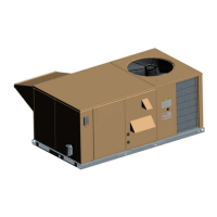
OPTIONAL ECONOMIZER RAIN HOOD
The following procedure should be used when assembling an
economizer rain hood onto a unit. Refer to Figure 3. The out-
door and return air dampers, damper actuator, the linkage
and all the controls are factory mounted as part of the econo-
mizer option.
Make sure that all screws are replaced on the unit
to maintain an air-tight seal.
When connecting electrical power and control wiring
to the unit, waterproof type connectors MUST BE
USED so that water or moisture cannot be drawn
into the unit during normal operation. The above
waterproofing conditions will also apply when install-
ing a field-supplied disconnect switch.
TABLE 2: PHYSICAL DATA
MODELS
DHE
036 048 060
EVAPORA-
TOR
BLOWER
CENTRIFUGAL BLOWER (Dia. x Wd.
in.)
FAN MOTOR HP
12 x 10
1.5
12 x 10
1.5
12 x 10
1.5
EVAPORA-
TOR
COIL
ROWS DEEP 4 4 4
FINS PER INCH 13 13 13
FACE AREA (Sq. Ft.) 4.3 5.1 5.1
CONDENSER
FAN
PROPELLER DIA. (in.) 24 24 24
FAN MOTOR HP 1/2 1/2 1/2
NOM. CFM TOTAL 4,500 4,200 4,200
CONDENSER
COIL
ROWS DEEP 2 2 2
FINS PER INCH 18 18 18
FACE AREA (Sq. Ft.) 17.1 17.1 17.1
AIR FILTERS
(SEE NOTE)
QUANTITY PER UNIT(15" x 20" x 1") 2 2 2
QUANTITY PER UNIT(14" X 25" X 1") 1 1 1
TOTAL FACE AREA (sq. ft.) 6.6 6.6 6.6
CHARGE REFRIGERANT 22 (lbs./oz.) 10 / 8 10 / 4 10 / 4
COMPRES-
SOR
QUANTITY PER UNIT (HERMETIC-
TYPE)
1/
RECPT
1/
RECPT
1/
RECPT
WEIGHTS (LBS)
Basic Unit
3 Ton 565
4 Ton 610
5 Ton 645
ACCESSORIES / OPTIONS
Electric Heat
(Nominal KW)
5-7KW 18
10 - 15 KW 23
20 - 30 KW 28
Economizer 50
Motorized Outdoor
Air Damper
26
Relief/Fixed
Air Damper
10
Roof Mounting Curb 92
Do Not loosen compressor mounting bolts.
 Loading...