5532522-UIM-B-0619
18 Johnson Controls Ducted Systems
NOTES:
1. Airflow expressed in standard cubic feet per minute (SCFM).
2.
Motor voltage at 115 V.
SECTION VIII: SAFETY CONTROLS
CONTROL CIRCUIT FUSE
A 3-amp fuse is provided on the control circuit board to protect the 24-
volt transformer from overload caused by control circuit wiring errors.
This is an ATO 3, automotive type fuse and is located on the control
board.
BLOWER DOOR SAFETY SWITCH
This unit is equipped with an electrical interlock switch mounted in the
burner compartment. This switch interrupts all power at the unit when
the panel covering the blower compartment is removed.
Electrical supply to this unit is dependent upon the panel that covers the
blower compartment being in place and properly positioned.
AUXILIARY LIMIT SWITCH
The switch is mounted on the burner assembly. If the temperature in the
burner exceeds its set point, the gas valve is de-energized. The opera-
tion of this control indicates a malfunction in the combustion air blower,
heat exchanger or a blocked vent pipe connection. Corrective action is
required.
PRESSURE SENSOR
This furnace is supplied with a pressure sensor, which monitors the flow
through the combustion air/vent piping system.
LIMIT CONTROLS
There is a high temperature limit control located on the furnace vesti-
bule panel near the gas valve. This is an automatic reset control that
provides over temperature protection due to reduced airflow. This may
be caused by:
1. A dirty filter.
2. If the indoor fan motor should fail.
3. Too many supply or return registers closed or blocked off.
The control module will lockout if the limit trips 5 consecutive times. If
this occurs, control will reset & try ignition again after 1 hour.
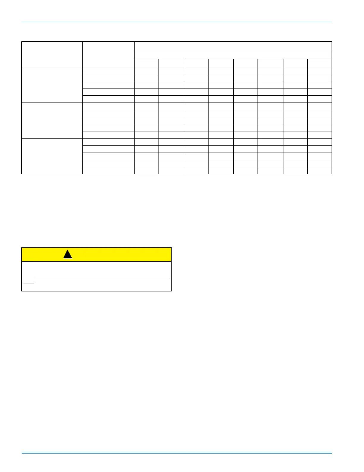
Table 11: Blower Performance CFM - Any Position (without filter)
Models Speed
Airflow Data (SCFM)
1, 2
Ext. Static Pressure (in. H2O)
0.1 0.2 0.3 0.4 0.5 0.6 0.7 0.8
060A12
High 1363 1328 1282 1257 1211 1180 1145 1100
Medium High 1161 1128 1083 1045 999 959 916 876
Medium 974 941 898 859 811 762 720 667
Medium Low 796 758 714 664 612 562 516 464
Low 720 685 636 589 529 473 431 375
080C16
High 1780 1730 1690 1650 1604 1574 1534 1501
Medium High 1576 1540 1504 1455 1408 1359 1316 1268
Medium 1443 1401 1357 1312 1258 1216 1163 1114
Medium Low 1259 1211 1164 1114 1065 1011 950 894
Low 1080 1030 978 927 872 816 757 680
100C20
High 2197 2138 2096 2052 2007 1958 1904 1869
Medium High 1767 1736 1696 1659 1611 1560 1516 1468
Medium 1581 1521 1476 1442 1400 1344 1295 1250
Medium Low 1406 1358 1316 1269 1222 1177 1131 1087
Low 1205 1146 1098 1039 993 939 890 820
CAUTION
Main power to the unit must still be interrupted at the main power dis-
connect switch before any service or repair work is to be done to the
unit.
Do not rely upon the interlock switch as a main power discon-
nect. Blower and burner must never be operated without the blower
panel in place.
!
 Loading...