251933-YTG-J-1009
100 Johnson Controls Unitary Products
ZF/ZR/XP036-060 Disconnect
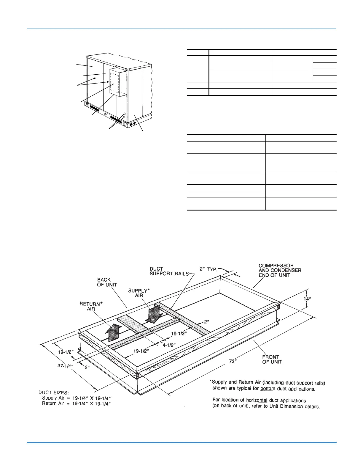
ZF/ZR/XP036-060 Roof Curb Dimensions
Disconnect Switch Location
and Motor Access Panel for
Unit with “Belt-Drive” Option
Control Box Access
A,B
Wiring Entry
(See Detail “B”)
Mounting Bracket for
Disconnect Switch
(Field Supplied)
Field-Supplied Disconnect
Switch Location
Blower Motor Access
Filter Access
Dot Plugs
ZF/ZR/XP036-060 Utilities Entry
Hole Opening Size (Dia.) Used For
A7/8” KO
1
1. Opening in the bottom to the unit can be located by the
slice in the insulation.
Control Wiring
2
2. Do not remove the 2” knockout ring.
Side
Bottom
B2” KO
1
Power Wiring
Side
Bottom
C 1-5/8” KO Gas Piping (Front)
D 1-1/2” KO Gas Piping (Bottom)
ZF/ZR/XP036-060 Minimum Clearances
Location Clearance
Front
24” (Cooling/Electric Heat)
32” (Gas Heat)
Rear
12” (Less Economizer)
36” (With Economizer or Fixed
Air/Motorized Damper)
Left Side (Filter Access)
24” (Less Economizer)
36” (With Economizer)
Right Side (Cond. Coil) 24”
Below Unit
1
1. Units may be installed on combustible floors made from
wood or class A, B, or C roof covering material.
0”
Above Unit
2
2. Units must be installed outdoors. Overhanging structures
or shrubs should not obstruct condenser air discharge
outlet.
72” (For
Condenser Air Discharge)