Maintenance and
Disassembly
Page 40
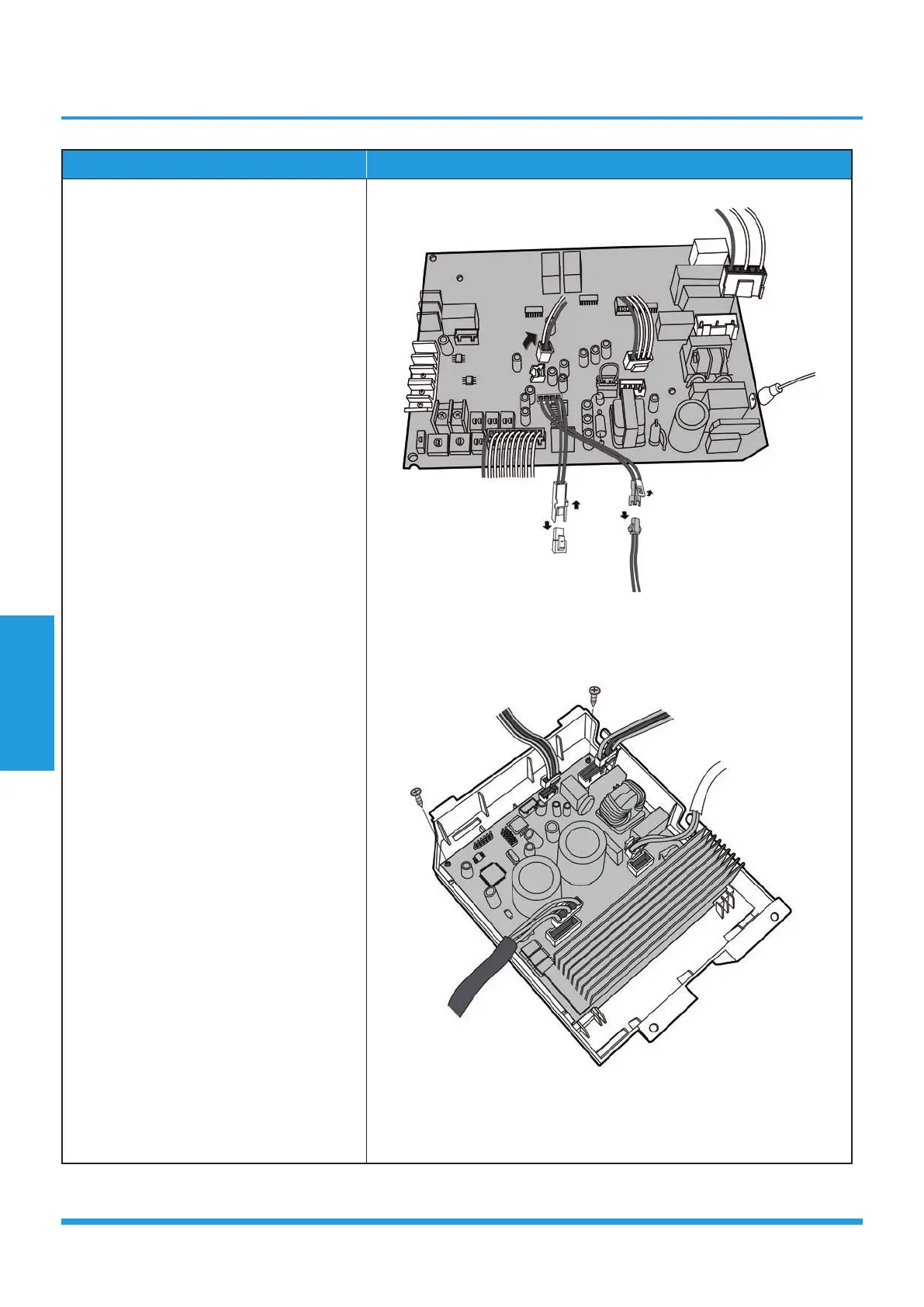
Procedure Illustration
3) Disconnect the connectors and then
remove the front main control board.
(see CJ_A6_003)
4) Turn over the electronic control box.
Disconnect the connectors and remove
the 2 screws of rear main control board.
(see CJ_A6_004)
CJ_A6_003
CJ_A6_004
Note: This section is for reference only. Actual unit appearance may vary.
 Loading...