Table 16: Chiller hardware torque values
Torque valueLocation YVAM
model
Description P/N SAP Quantity
lb·ft N•m
Mod A 021-33185-090 731065Suction line flange at
compressor
Mod B
M24 X 3 / 90 mm long
021-35824-090 5402072
12 230 312
Mod A M20 X 2.5 / 70 mm
long
021-33184-070 731064 8Discharge line flange at
compressor
Mod B M20 X 2.5 / 90 mm
long
021-35824-090 5402049 12
150 204
Liquid line shutoff valve inlet
flange
All M16 X 2 / 60 mm long 021-35816-060 5399748 4 55 75
Liquid line shutoff valve outlet
flange
All 5/8 UNC 3.75 in. long 021-32310-030 555972 4 65 89
Liquid line variable orifice
butterfly valve flanges
All 5/8 UNC Stud 5.5 in.
long
021-12760-000 729652 8 45 61
Compressor mounting feet at
compressor
All M20 X 2.5 / 60 mm
long
021-33184-060 731063 4 441 598
Compressor mounting feet at
unit base
All 3/8 UNC / 1.5 in. long 021-19305-024 564228 8 43 59
Refrigerant tubing reassembly
Use the following procedures to reassemble the chiller refrigerant piping.
Assembly of straight thread O-ring port fittings
The male and female ends of SAE and ISO 6149 straight thread O-ring ports have UN/UNF or metric
straight threads. An elastomeric O-ring is fitted to the male end. During assembly, the O-ring is
firmly sandwiched between the angular sealing surface of the female port and the shoulder of the
male end. As a result, sealing is affected and maintained by the O-ring compression, which results
from the clamping force generated by tightening. The straight threads do not offer sealing action,
but they provide the resistance, or holding power, for service pressure.
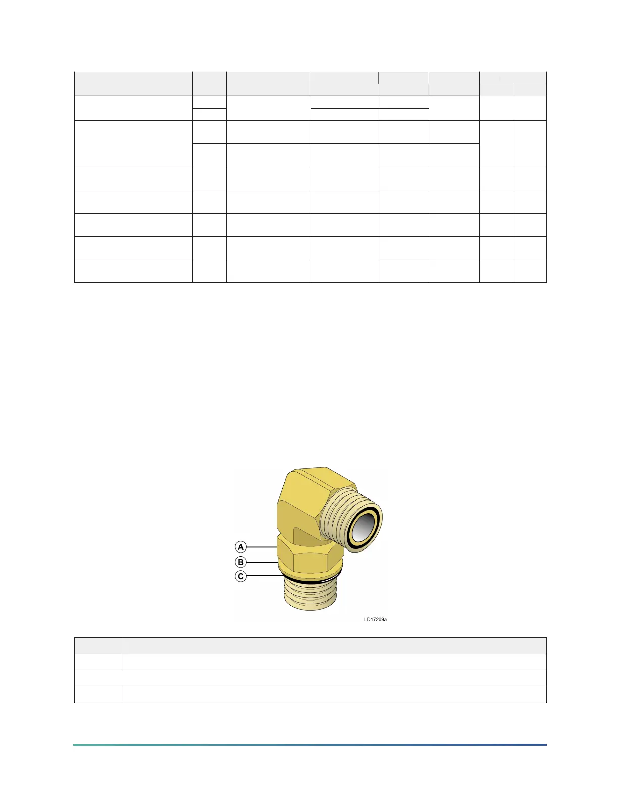
Figure 39: Adjustable end fitting
Callout Description
A Locknut
B Back-up washer
C O-ring
YVAM Air-Cooled Centrifugal Liquid Chiller42
 Loading...