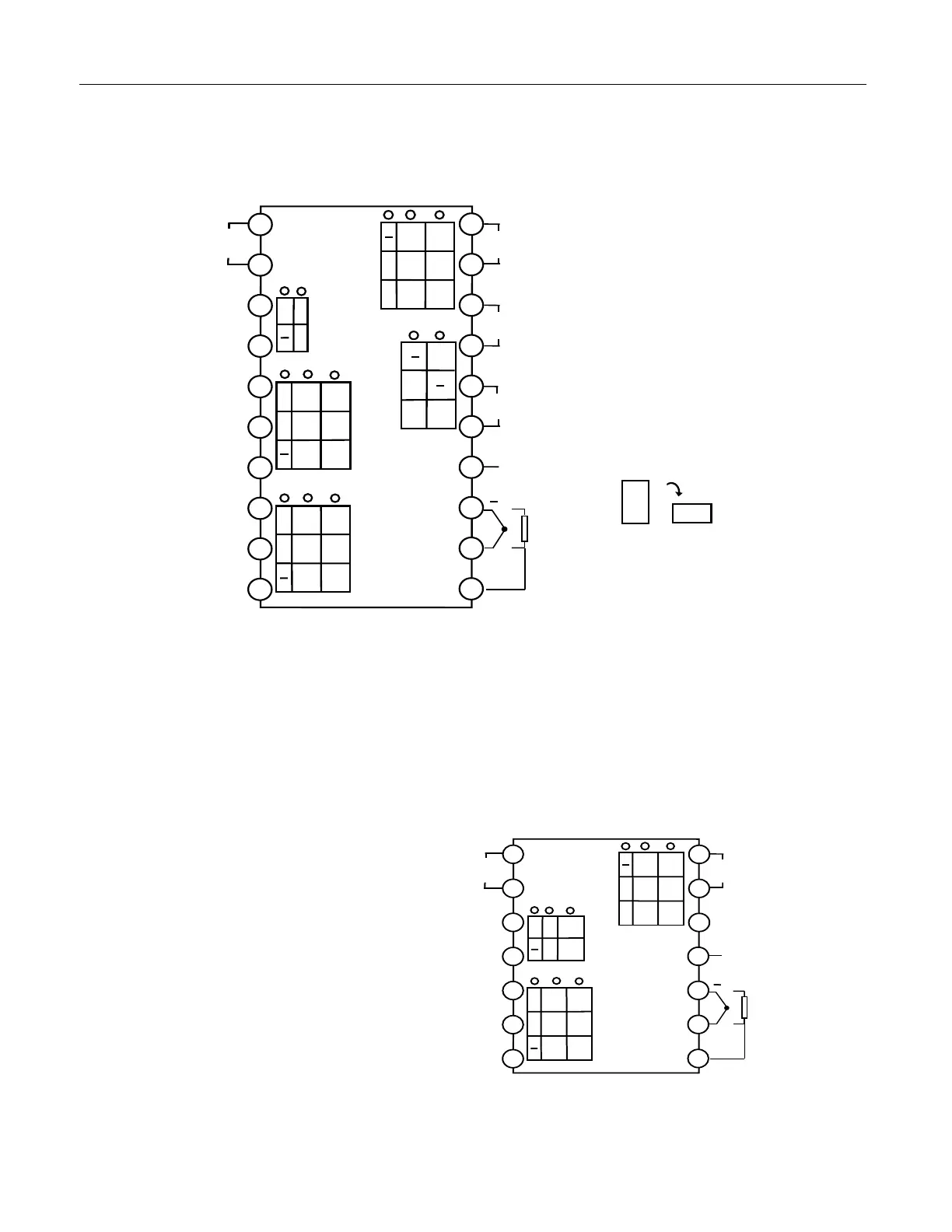
3. Rear Terminal Layout and Wiring
Wiring graph for instruments except D and D2 dimension.
Thyristor trigger output
(
K1/K3
)
Thyristor trigger output
(
K3
)
Thyristor trigger output(K3)
The graph suits for upright instruments
with dimension A, C or E
For instruments with dimension F, just
clockwise rotate the graph 90 degree,
and the numbers of the terminals keep
the same.
Note 1: For linear voltage input, if the range is below 1V, connect to terminals 19 and 18. 0~5V or 1~5V
signal can be inputted from terminals 17 and 18.
Note 2: 4~20mA linear current signal can be transformed to 1~5V voltage signal by connecting a 250 ohm
resistor, and then be inputted from terminals 17 and 18. If I4 module is installed in MIO socket, 4~20mA
signal can be inputted from terminals 14+ and 15-, and 2-wire transmitter can be inputted from terminals
16+ and 14-.
Note 3: The compensation wires for different kinds of thermocouple are different, and should be directly
connect to the terminals. When the internal auto compensation mode is used, connecting the common
wire between the compensation wire and the terminals will cause measurement error.
Wiring graph of D dimension instruments
(72×72mm)
Note 1: Linear voltage signal of range below
1mV should be inputted from terminals 13 and
12, and signal of 0~5V and 1~5V should be
inputted from terminals 11 and 12.
Note 2: 4~20mA linear current signal can be
converted to 1 ~ 5V voltage signal by
connecting a 250 ohm resistor and inputted
from terminals 11 and 12.
Note 3: S or S4 module can be installed in COMM socket for communication. If relay, TRIAC no contact
switch, or SSR driver voltage output module is installed in COMM, it can be used as alarm output. If I2
Thyristor trigger ou
tput(K1)
 Loading...