30
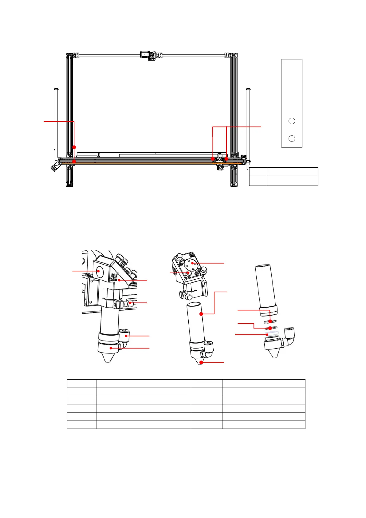
Figure 3-18 Removal of fixation block Diagram
3.1.4.9 Cutting head installation
At ex-factory, to ensure safety and prevent the laser head from being polluted during transportation, the
cutting head (focus canister) of some types of machine are individually packaged and kept. During installation of
the equipment, they should be replaced back.
Figure 3-19 Cutting Head Structure Diagram
Lockup for some types machine
Light route adjusting bolt



 To Next Page