81
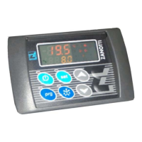
7.2. Setting the work set point:
Press the SET button: on the red display the current value flashes and Set1 appears on the yellow display; press
the up/down buttons to change the current value. Press SET again or wait 10 seconds to save the new value.
7.3 Programming the parameters
To enter the programming mode press for 5 seconds. The first parameter is reached, whose label is
shown on the yellow display and value on the red display.
To change a parameter, use the up/down buttons to reach the parameter desired. Press the SET button, the
current value flashes, use the up/down buttons to set the new value. Then press SET again to go to the following
parameter. Wait 10 seconds to leave the programming mode automatically.
LABEL DESCRIPTION Cold Heat/Cold Heat
pump
Set Set point
Set2 Set point 2
FuS Operating modes: CL = cold, C-H = cold/heat, HPU= heat
pump
CL C-H HPU
Dt Hysteresis 2 2 2
IS Min. set point -20 -20 -20
SS Max. set point 30 30 30
oF Sensor calibration 0 0 0
AL Low temperature alarm 5 5 5
AH High temperature alarm 30 30 30
dA Alarm differential 2 2 2
SA Alarm cut out at power on 4 4 4
ALd Temperature alarm delay 30 30 30
Tdf Defrost mode Std Std Std
dS Max defrost time 5 5 5
Fdt Dripping time 0 0 0
Fnd Fan delay after defrost 1 1 1
EdA Alarm cut out after defrost 30 30 30
Sd Anti-short cycle (standby mode only) 2 2 2
dF Interval between defrosts 3 3 3
dFd Display during defrost it it it
dAd Display delay after defrost 30 30 30
Bt Battery voltage selection 12/24 12/24 12/24
PAb Differential for battery voltage pre-alarm 0,7/1,5 0,7/1,5 0,7/1,5
Ab Differential for battery voltage alarm 1,5/3 1,5/3 1,5/3
Abd Differential for battery alarm 0,8/1,5 0,8/1,5 0,5/1,5
tF Standby clutch delay 5 5 5
Standby clutch delay (only for FZ213) *0 *0 *0
bb Start delay after alarm Ab 1 1 1
tS Temperature measurement unit C C C
rES Display of integer / decimal number de de de
LPP Input polarity of low pressure switch OP OP OP
LPn Number of interventions of low pressure switch 10 10 10
LPd Interval between interventions of low pressure switch 60 60 60
HPP Input polarity of high pressure switch OP OP OP
HPn Number of interventions of high pressure switch 10 10 10
HPd Interval between interventions of high pressure switch 60 60 60
dFP Input polarity of defrost end CL CL CL
HtP Input polarity of overload relay OP OP OP
Htn Number of interventions of overload relay 3 3 6
Htd Interval between interventions of overload relay 60 60 60
Htt Start delay after overload relay intervention 2 2 15
HOP Output polarity of 4-way valve (heat pump) CL CL CL
 Loading...