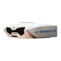
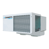
Refrigeration unit
Zero Z120b
INSTALLATION MANUAL
rev.01
3.9.2 Device connection
The wires are marked with an identification number which is also shown on the wiring
diagram.
• Connect the M5 and M8 fans (3, Figure 34) of the evaporators, depending on the version.
• Connect the defrosting valve YS (5) - if supplied.
• Connect the YI injection valve (4) - if present.
• Connect the red cable R to the FGS (1) battery protection fuse (positive pole)
• Connect the other end of the FGS fuse to the battery positive pole.
• Connect the positive battery cable, complete with FGS fuse, to the main KMC relay, as indicated
in the paragraph 3.9.3
• Connect the black cable B (2) to the battery negative pole.
• Install the FSC fuse under key (6), as indicated in the paragraph 3.9.4.
• Connect the exhaust resistance ES (6), as indicated in paragraph 3.9.5- if present.



 To Next Page