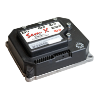
This document describes the SEM-X Chopper, an electronic industrial device manufactured by ZAPI. The SEM-X is designed for use in commercially available machines and offers a range of features for efficient and safe operation.
Function Description
The SEM-X Chopper is a control unit for separately excited DC motors, providing precise control over speed, braking, and direction. It integrates various safety and protection features to ensure reliable operation. The device is designed to handle rapid reversal and conforms to Directive prEN 1175 for direction orientation.
Key functional aspects include:
- Speed Control: Optimum sensitivity at low speeds, with speed reductions in both directions.
- Regenerative Braking: Based on deceleration ramps, in every condition.
- Three Different Modes of Braking: Release Braking, Inversion Braking, and Deceleration Braking.
- Speed Control During Descent: The motor speed follows the accelerator, and the chopper automatically brakes if the motor speed overcomes the accelerator set point, providing optimum performance on a gradient.
- Starts on a Ramp without Roll Back: Even without an electric brake.
- Key Switch Operation: When the key switch is closed, if the motor is rotating, the chopper controls the speed and automatically brakes and keeps the motor at a very low speed during descent on a gradient. This ensures safety and is not driver-dependent.
- Main Contactor: Opens after 60 seconds of stand-by condition.
- Self-Diagnosis: Indication of fault shown via flashing Red LED (without Console).
- Parameter Modification: Parameters are modified via Digital Console, with the specific description available.
- Internal Hour Meter: Displays on the Console.
- Memory of Last 5 Alarms: With relative Hour meter count and chopper temperature displayed on the Console.
- Test Function: Within Console for checking main parameters.
- High Motor and Battery Efficiency: Due to High Frequency Switching.
- MDI Intrument Connection: Possible to connect SEM-X to MDI instrument.
Important Technical Specifications
The SEM-X Chopper is available in different versions with varying current capacities and voltage drop characteristics.
General Characteristics:
- Chopper for Separately Excited DC motors: 0.35 ÷ 0.8kW
- Regenerative Braking: Yes
- Voltage Range: 24VDC
- Maximum Field Current (all versions): 35 A
- Armature Switching Frequency: 16KHz
- Field Switching Frequency: 16KHz
- Maximum Ambient Temperature: + 40°C
- Minimum Ambient Temperature: -30°C
- Maximum Temperature of Chopper: + 90°C
Versions and Current Specifications:
| VERSIONS |
MAXIMUM CURRENT |
VOLTAGE DROP IN FULL CONDUCTION |
| 24V |
90A (3') |
0.14V at 35A, 25°C |
| 24V |
110A (2') |
0.14V at 35A, 25°C |
Potentiometer Specifications:
- Potentiometer wired in the 3 - Wire Configuration.
- CPOT (A2) signal ranges from 0 to 10V.
- Minimum Potentiometer Resistance: 500Ω
- Maximum Potentiometer Resistance: 10kΩ
- Faults can occur if the potentiometer is out of this range.
Safety & Protection Features:
- Connection Errors: All inputs are protected against connection errors.
- Thermal Protection: If chopper temperature exceeds 75°C, maximum current reduces proportionally. Temperature never exceeds 90°C (current reduced to 80% below -10°C).
- Low Battery Charge: When battery charge is low (≤20%) and "BATTERY CHECK" is ON, maximum current reduces to 50% and speed to 60%.
- Protection Against Accidental Start-up: Requires a precise sequence of operations before machine start. Drive requests must be made after closing the key switch.
- Protection Against Uncontrolled Movements: Line Contactor will not close if Power Unit or Logic is not functioning perfectly.
- Main / Line Contactor: Fitted to protect chopper against reverse battery polarity and for safety.
- External Agents: Chopper is protected against dust and liquid spray to IP54 degree.
Usage Features
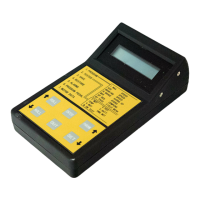
The SEM-X Chopper is designed for ease of use and configuration through a Digital Console.
Console and Connection:
- The Digital Console is connected to the 'B' connector of the SEM-X Chopper.
- Pay attention to the polarity of the Console Connector; the bevel on the connector should be uppermost.
Standard Console Menu:
The console provides access to various parameters and settings, organized into a main menu with sub-menus for parameter change, set options, adjustments, tester, alarms, program VACC, and motor data.
Programmable Functions (Options):
- Hour Counter: Registers travel time (RUNNING) and time when key switch is closed (KEY ON).
- Quick Inversion: Activated by Belly Button (immediate) or timed (maximum 3 seconds).
- Aux Output #1: A11 output can be used for controller monitor function or to drive an electromechanical brake.
- Battery Check: Alarm indication for speed reduction and current reduction when battery charge is <20%.
- Set Accel Type: Standard 0÷5V potentiometer input or 5÷0V potentiometer input.
- Backing Function: Input A9 can be used as enable backing input, or as speed reduction; no backing function available.
- Handle Switch: A4 can be a tiller input (correct start if closed at key on; no delay if switched off), or a seat input (no incorrect start if closed at key on; programmable delay if switched off).
Parameter Programming:
Parameters can be modified using the Digital Console. Default settings can be restored. Key parameters include:
- ACC. DELAY: Acceleration ramp.
- DECELER DELAY: Deceleration ramp according to pedal position.
- RELEASE BRAKING: Deceleration ramp when travel request is released.
- INVERSION BRAKING: Deceleration ramp when Direction Switch is inverted during travel.
- CUTBACK SPEED 1 & 2: First and second speed reduction, active when H&S is active or when DIGITAL INPUT2 is active.
- MAX SPEED FORW & FWD FINE: Maximum forward speed.
- MAX SPEED BACK & BACK FINE: Maximum reverse speed.
- TRACTION I MAX: Maximum controller current.
- ARMA NOM.CURR: Nominal Armature Current.
- FIELD NOM. CURR: Nominal Field Current.
- CREEP SPEED: Minimum speed.
- FIELD CURR MAX: Maximum field current.
- BACKING TIME: Maximum backing function time.
- BACKING SPEED: Fixed speed when backing function is active.
- SEAT MICRO DELAY: Time for which seat switch opening is ignored.
- WEAK DROPOUT: Parameter for armature current increase and nominal field current decrease.
Menu Special Adjust:
- SET TEMPERATURE: Adjusts chopper temperature.
- MAXIMUM CURRENT: Adjusts maximum current level of chopper.
- ADJ FIELD NOM FW & BW: Adjusts field nominal current in forward and backward direction.
Menu Hardware Setting:
- SET CURRENT: Calibrates armature current.
- SET FLD CURRENT: Calibrates field current.
- ADJUSTMENT #01 & #02: Adjusts 90% and 20% threshold of battery discharge table.
- AUX FUNCTION 1: Load hour meter from MDI option (ON/OFF).
- CHECK UP TYPE: Programmable check up function (no check up, warning after HM hours, speed reduction, stop of functions).
- CHECK UP HOURS: Sets check up alarm time.
Menu Adjustment:
- ADJUST BATTERY: Sets correct battery voltage level.
- THROTTLE O ZONE, X POINT, Y POINT: Sets pedal curve type.
SEM-X Diagnostics:
The microprocessor monitors the chopper and carries out diagnostic procedures. Diagnosis is made in 4 points:
- Key Switch Closing: Checks Watch Dog Circuits, current sensors, VMN point, Main Contactor Driver, switch sequence for operation, and output of accelerator or tiller.
- Standby Diagnosis: Checks VMN Point, Main Contactor Driver, Current Sensor, Watchdog, Brake, Vfield, NPOT.
- Diagnosis During Operation: Checks Watchdog, VMN Point, Current (field and armature), Main Contactor, Brake, NPOT.
- Continuous Diagnosis: Checks Chopper temperature, Battery Voltage.
Diagnosis is provided in 3 ways: Red Led connected to Connector B will flash a certain number of times for a given Alarm, Digital Console, or MDI. A permanent Alarm will be displayed on the Console immediately. An intermittent Alarm will be recorded in the Alarm library.
Thermal Considerations:
- Heat generated by power block must be dissipated. Compartment must be ventilated, and heat sink materials ample.
- Heat sink material and system should be sized for performance requirement. Abnormal ambient air temperatures should be considered.
- Thermal energy dissipated by power block module varies and is dependent on current drawn and duty cycle.
Maintenance Features
Regular maintenance is crucial for the longevity and reliable operation of the SEM-X Chopper.
Periodic Maintenance to be Repeated at Times Indicated:
- Contactors' Moving and Fixed Contacts: Check wear and condition every 3 months.
- Foot Pedal or Tiller Microswitch: Using a suitable test meter, confirm no electrical resistance between contacts. Switches should operate with a firm click sound. Microswitches should be checked every 3 months.
- Battery Cables, Chopper Cables, and Motor Cables: Ensure insulation is sound and connections are tight. Cables should be checked every 3 months.
- Mechanical Operation of Pedal or Tiller: Return springs are OK. Potentiometers wind up to their full or programmed level. Check every 3 months.
- Mechanical Operation of Contactor(s): Moving contacts should be free to move without restriction. Check every 3 months.
- Spare Parts: Checks should be carried out by qualified personnel, and any replacement parts used should be original. Beware of NON ORIGINAL PARTS.
- Electronic Controller Installation: Installation should be made according to diagrams included in this Manual. Any variations or special requirements should be made after consulting a Zapi Agent. The supplier is not responsible for any problem that arises from wiring methods that differ from information included in this Manual.
- Safety: During periodic checks, if a technician finds any situation that could cause damage or compromise safety, the matter should be bought to the attention of a Zapi Agent immediately. The Agent will then take the decision regarding operational safety of the machine.
- Battery Powered Machines: Remember that Battery Powered Machines feel no pain.
- Faulty Electronic Controller: NEVER USE A VEHICLE WITH A FAULTY ELECTRONIC CONTROLLER.
Recommended Spare Parts for SEM-X:
- C16519: Protected 150A Fuse.
- C16503: Protected 200A Fuse.
- C16520: 6.3A 5x20mm Control Circuit Fuse.
- C12404: 16 Way Molex Minifit Connector.
- C12777: Insert for Molex Minifit Connectors.
- C29543: SW 80 24V CO Single Pole Contactor.