Page 23
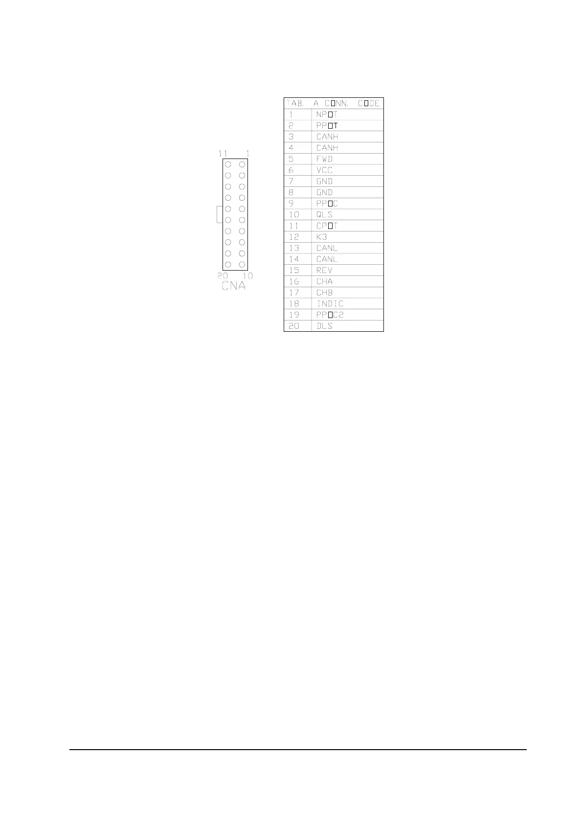
8.2 CNA CONNECTOR
1 NPOT This is the lower voltage connection for the steer feedback
potentiometer. It's internally connected to GND through a 470
Ohms resistance.
2 PPOT This is the higher voltage connection for the steer feedback
potentiometer. It's internally connected to a 5Vdc reference through
a 470 Ohms resistance .
3 CANH This is the high reference of the CAN interface.
4 CANH Same of pin #3. Pin #3 and #4 are internally connected together.
5 FWD A request to travel in the Drive Unit direction must provide a signal
on this input, either at battery positive or battery negative. Either
level may be selected configuring Jumper J2.
6 VCC Optional encoder supply. When an encoder is used it may be
supplied through this pin. The output voltage is selected through the
jumper J8 (see. 5).
7 GND This is internally connected to ground (battery minus) reference. It
may be used for the GND reference of the optional encoder or for
the stepper motor (manual command device).
8 GND This is internally connected to ground (battery minus) reference. It
may be used for the GND reference of the steer angle direction Led
gauge.
9 PPOC Not Used. This is the higher voltage connection for a handwheel set
point potentiometer. This steering option requires modifications
on the logic card and cannot be carried out when a tacho-
generator or a stepper motor card is chosen. This pin is internally
connected to a 5Vdc reference through a 470 Ohms resistance.