Page 6
2.2.b Potentiometer
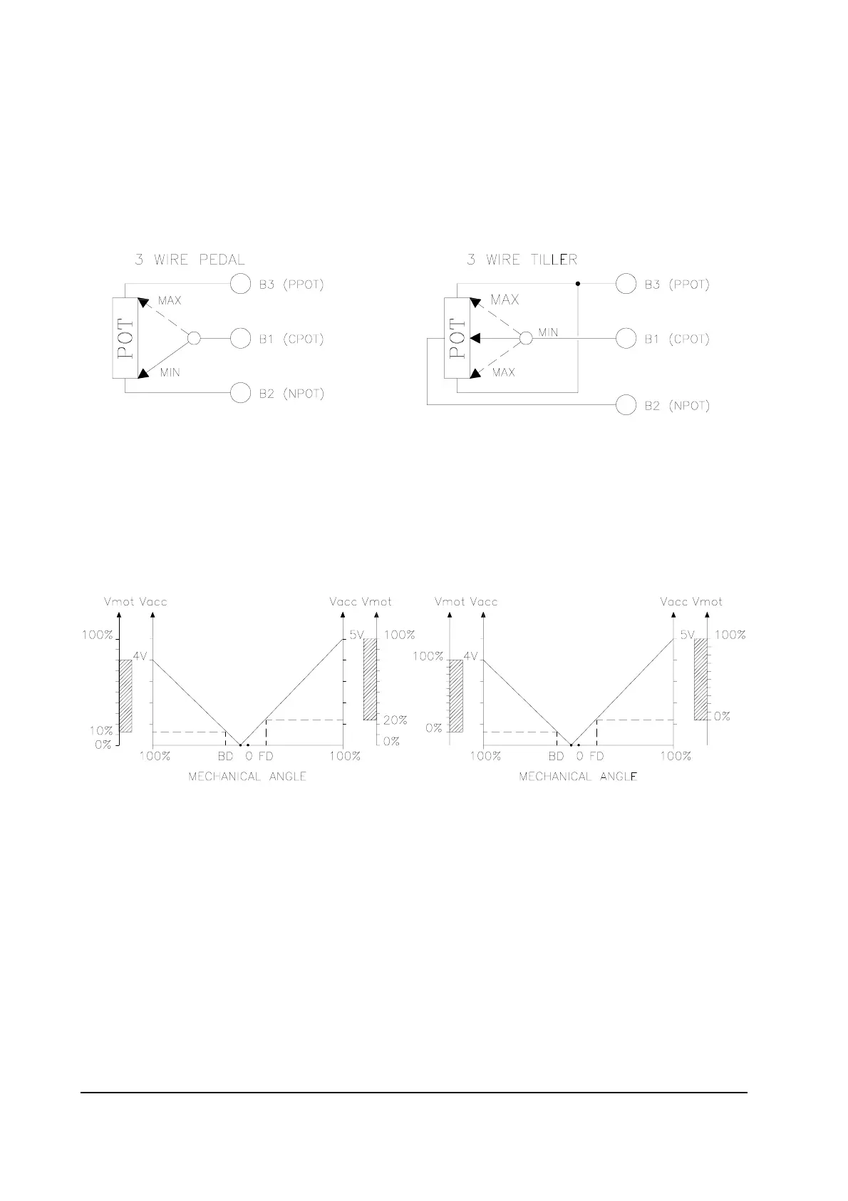
The Potentiometer should be wired in the 3 - Wire Configuration.
CPOT (B1) signal ranges from 0 to 10V.
Minimum Potentiometer Resistance : 500W
Maximum Potentiometer Resistance : 10kW
Faults can occur if the potentiometer is out of this range.
The Procedure for automatic potentiometer signal aquisition is carried out using the
Console. This enables adjustment of the minimum and maximum useful signal level
(PROGRAM VACC function), in either direction. This function is unique when it is
necessary to compensate for asymmetry with the machanical elements associated with
the potentiometer, especially relating to the minimum level.
The two graphs show the output voltage from a non-calibrated potentiometer with
respect to the mechanical “zero” of the control lever. MI and MA indicate the point
where the direction switches close. 0 represents the mechanical zero of the rotation.
The Left Hand graph shows the relationship of the motor voltage without signal
aquisition being made. The Right Hand Graph shows the same relationship after signal
aquisition of the potentiometer.