Technical Instructions
installation Guide
System New Bora
MT-IS-GAI-NWB.01-E
del 01/10/2013
Pag. 14 di 26
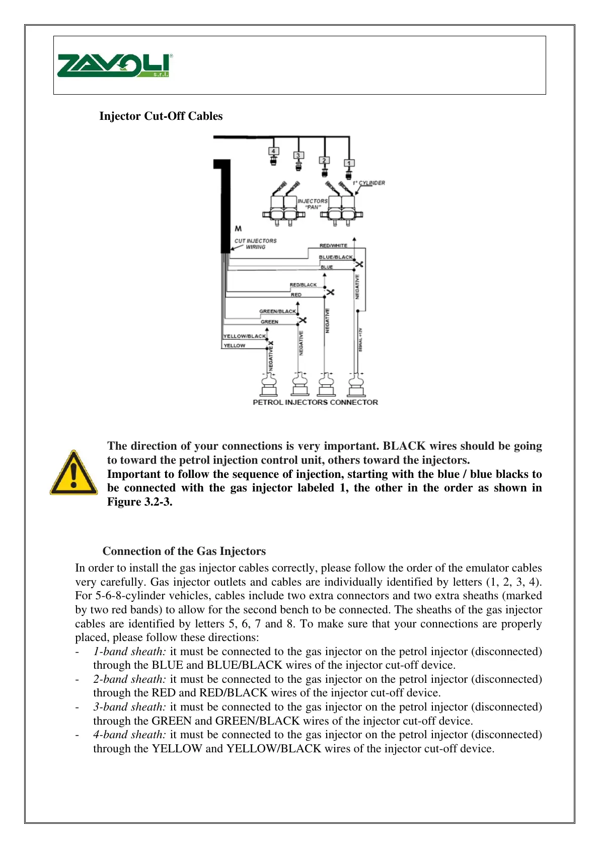
3.2 Injector Cut-Off Cables
Fig. 3.2-3
The direction of your connections is very important. BLACK wires should be going
to toward the petrol injection control unit, others toward the injectors.
Important to follow the sequence of injection, starting with the blue / blue blacks to
be connected with the gas injector labeled 1, the other in the order as shown in
Figure 3.2-3.
3.3 Connection of the Gas Injectors
In order to install the gas injector cables correctly, please follow the order of the emulator cables
very carefully. Gas injector outlets and cables are individually identified by letters (1, 2, 3, 4).
For 5-6-8-cylinder vehicles, cables include two extra connectors and two extra sheaths (marked
by two red bands) to allow for the second bench to be connected. The sheaths of the gas injector
cables are identified by letters 5, 6, 7 and 8. To make sure that your connections are properly
placed, please follow these directions:
- 1-band sheath: it must be connected to the gas injector on the petrol injector (disconnected)
through the BLUE and BLUE/BLACK wires of the injector cut-off device.
- 2-band sheath: it must be connected to the gas injector on the petrol injector (disconnected)
through the RED and RED/BLACK wires of the injector cut-off device.
- 3-band sheath: it must be connected to the gas injector on the petrol injector (disconnected)
through the GREEN and GREEN/BLACK wires of the injector cut-off device.
- 4-band sheath: it must be connected to the gas injector on the petrol injector (disconnected)
through the YELLOW and YELLOW/BLACK wires of the injector cut-off device.
Přestřižení kabelů ke vstřikovačům
Polarita vašeho připojení je velmi důležitá. Černý drát by měl jít směrem k benzínové ŘJ,
ostatní směrem ke vstřikovačům.
Důležité je následovat sekvenci vstřikování, začněte s modrým/modro-černým připojeným
k plynovému vstřikovači označenému jako 1, další v pořadí jak zobrazuje obr. 3.2.3.
Zapojení plynových vstřikovačů
Aby byly kabely kplynovým vstřikovačům nainstalovány správně, prosím velmi pečlivě sledujte pořadí kabelů
emulátoru. Vývody a kabely plynových vstřikovačů jsou popsány individuálně (1,2,3,4). Pro 5-6-8 válcová
vozidla obsahují kabely dva konektory navíc a dvě pouzdra (o značené dvěma črvnými proužky) aby bylo
možné připojit druhou lištu. Krytka kabelů plynových vstřikovačů jsou označeny 5,6,7 a 8. Ujištěte se že
konektory jsou správně umístěny a postupujte podle těchto instrukcí:
1-jeden pásek na pouzdru: musí být připojen na plynový vstřikovač a k benzínovému vstřikovači (odpojený)
prostřednictvím modrého a modro-černého drátu k odstřiženému zařízení.
2-pásky na pouzdru: musí být připojen na plynový vstřikovač a k benzínovému vstřikovači (odpojený)
prostřednictvím červeného a červeno-černého drátu k odstřiženému zařízení.
3-pásky na pouzdru: musí být připojen na plynový vstřikovač a k benzínovému vstřikovači (odpojený)
prostřednictvím zeleného a zeleno-černého drátu k odstřiženému zařízení.
4-pásky na pouzdru: musí být připojen na plynový vstřikovač a k benzínovému vstřikovači (odpojený)
prostřednictvím žlutého a žlutoo-černého drátu k odstřiženému zařízení.


 To Next Page