Technical Instructions
installation Guide
System New Bora
MT-IS-GAI-NWB.01-E
del 01/10/2013
Pag. 7 di 26
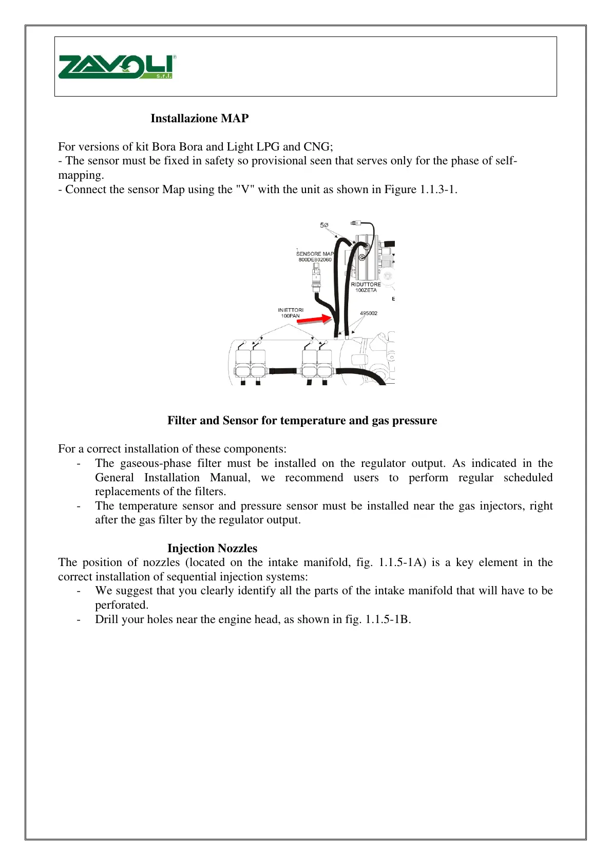
1.1.3 Installazione MAP
For versions of kit Bora Bora and Light LPG and CNG;
- The sensor must be fixed in safety so provisional seen that serves only for the phase of self-
mapping.
- Connect the sensor Map using the "V" with the unit as shown in Figure 1.1.3-1.
Fig. 1.1.3-1
1.1.4 Filter and Sensor for temperature and gas pressure
For a correct installation of these components:
- The gaseous-phase filter must be installed on the regulator output. As indicated in the
General Installation Manual, we recommend users to perform regular scheduled
replacements of the filters.
- The temperature sensor and pressure sensor must be installed near the gas injectors, right
after the gas filter by the regulator output.
1.1.5 Injection Nozzles
The position of nozzles (located on the intake manifold, fig. 1.1.5-1A) is a key element in the
correct installation of sequential injection systems:
- We suggest that you clearly identify all the parts of the intake manifold that will have to be
perforated.
- Drill your holes near the engine head, as shown in fig. 1.1.5-1B.
Pro verzi kitu LPG a CNG Bora a Bra Light;
- Čidlo musí být připevněno bezpečně provizorně, protože slouží jen pro fázi samomapování.
- Připojte sensor MAP s jednotkou s použitím "V" , jak je zobrazeno na obr. 1.1.3-1.
Filtr a čidlo teploty a tlaku
Pro správnou instalaci těchto komponent:
- Filtr plynné fáze musí být namontován na výstup regulátoru. Jak je znázorněno v obecném manuálu
montáže, doporučujeme uživatelům provádět pravidelné výměny filtru.
- Teplotní a tlakové čidlo musí být nainstalováno poblí plynových vstřikovačů, správně za filtrem u výstupu
regulátoru.
Umístění trysek (na sacím potrubí, obr. 1.1.5-1A) je klíčovým prvkem při správné instalaci sekvenčních
vstřikovacích systémů:
- doporučujeme, abyste si jasně označily všechny části sacího potrubí, které budou vrtány.
- Díry vrtejte v blízkosti motorové hlavy, viz obr. 1.1.5-1B.