Technical Instructions
installation Guide
System New Bora
MT-IS-GAI-NWB.01-E
del 01/10/2013
Pag. 4 di 26
1. Installation of Mechanical Parts
1.1 Component Location
Before installing your Bora or Bora Light (LPG) and Bora or Bora Light (CNG) system
components, find a location inside the engine chamber which allows for the following
operations to be easily completed:
1.1.1 Regulators
- Maintenance and adjustments.
- Inbound and outbound connections with the engine cooling liquid should be easily
accessible. Tubing should be kept as short as possible and should not be bent (fig. 1.1.1-2).
- The tube connecting the gas outlet on the regulator and the gas inlet on the injectors should
be kept as short as possible (as indicated in the General Installation Manual, the maximum
length is 700mm).
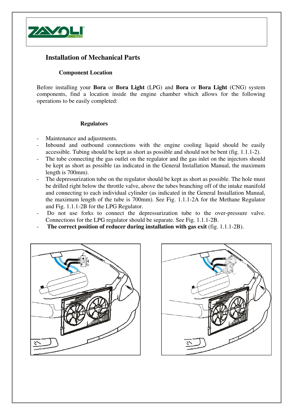
- The depressurization tube on the regulator should be kept as short as possible. The hole must
be drilled right below the throttle valve, above the tubes branching off of the intake manifold
and connecting to each individual cylinder (as indicated in the General Installation Manual,
the maximum length of the tube is 700mm). See Fig. 1.1.1-2A for the Methane Regulator
and Fig. 1.1.1-2B for the LPG Regulator.
- Do not use forks to connect the depressurization tube to the over-pressure valve.
Connections for the LPG regulator should be separate. See Fig. 1.1.1-2B.
- The correct position of reducer during installation with gas exit (fig. 1.1.1-2B).
Fig. 1.1.1-1 Fig. 1.1.1-2
Instalace mechanických částí
Před instalací kompnent systém BORA nebo BORA LIGHT (LPG) a Bora a Bora Light (CNG) nalezněte v
motorovém prostoru umístění, což umožní, aby následující činnoti bylysnadno dokončeny:
- údržba a nastaení.
- Příchozí a odchozí připojení k chladícímu okruhu motoru by mělo být snadno dostupné. Trubky by měly
být co možná nejkratší a neměly by být hnuté (obr. 1.1.1-2).
¨ Připojení trubky plynového vývodu na reduktoru a plynového vstupu na vstřikovačích by mělo být co
možná nejkratší ( jak je určeno v celkovém instalačním manuálu, max. délka je 700 mm).
- Odtlakovací trubka na regulátoru by měla být co možná nejkratší. Díra musí být vrtána přímo pod škrtícím
ventilem nad větvením sacího potrubí a připojena ke každému jednotlivému válci (jak je uedeno v Hlavním
manuálu montáže, mas. délka trubky je 700 mm). Viz ovr. 1.1.1-2A pro regulátor meatanu a 1.1.1-2B pro
regulátor LPG.
- Pro připojení odtlakovací trubky k přetlakovému ventilu nepoužívejte vidličky . Připojení k regulátoru LPG
by mělo být oddělené, Viz obr. 1.1.1-2B.
- Správná pozice reduktoru při instalaci s vývodem plynu (obr. 1.1.1-2B).