Page 6-18 105SL Maintenance Manual 32056L Rev. 2 12/4/01
SECTION 6 OPTION KITS
NOTES: The parallel port on the back of the printer is not operational when the
internal PrintServer II is installed. The hardware of the PrintServer II
mounting bracket covers the parallel port.
After you have finished installing the PrintServer II hardware; refer to the
appropriate section of the printer User’s Guide for information on
establishing a connection for your network type.
CAUTION:
OBSERVE PROPER ELECTROSTATIC SAFETY PRECAUTIONS WHEN
HANDLING ANY STATIC-SENSITIVE COMPONENTS SUCH AS PRINTED
CIRCUIT BOARDS AND PRINTHEADS.
1. Refer to RRP No. 1 on page 4-10 and place the power switch in the Off (O) position
and disconnect the AC power cord. Disconnect the data cables.
2. Refer to Figure 6-14. At the rear of the printer, remove the two screws and the blank
cover plate or an existing optional interface board positioned next to the serial and
parallel interface connectors.
3. Refer to RRP No. 2 on page 4-12 and remove the electronics cover.
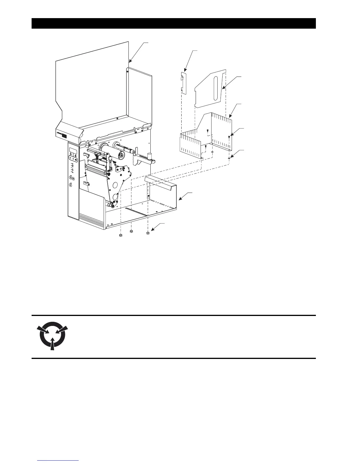
Figure 6-13. Internal Fanfold Supply Bin Installation