6.0 PRINCIPLES OF OPERATION
ZEKS Eclipse
TM
90-5,000ZPB Desiccant Dryers
www.zeks.com
8
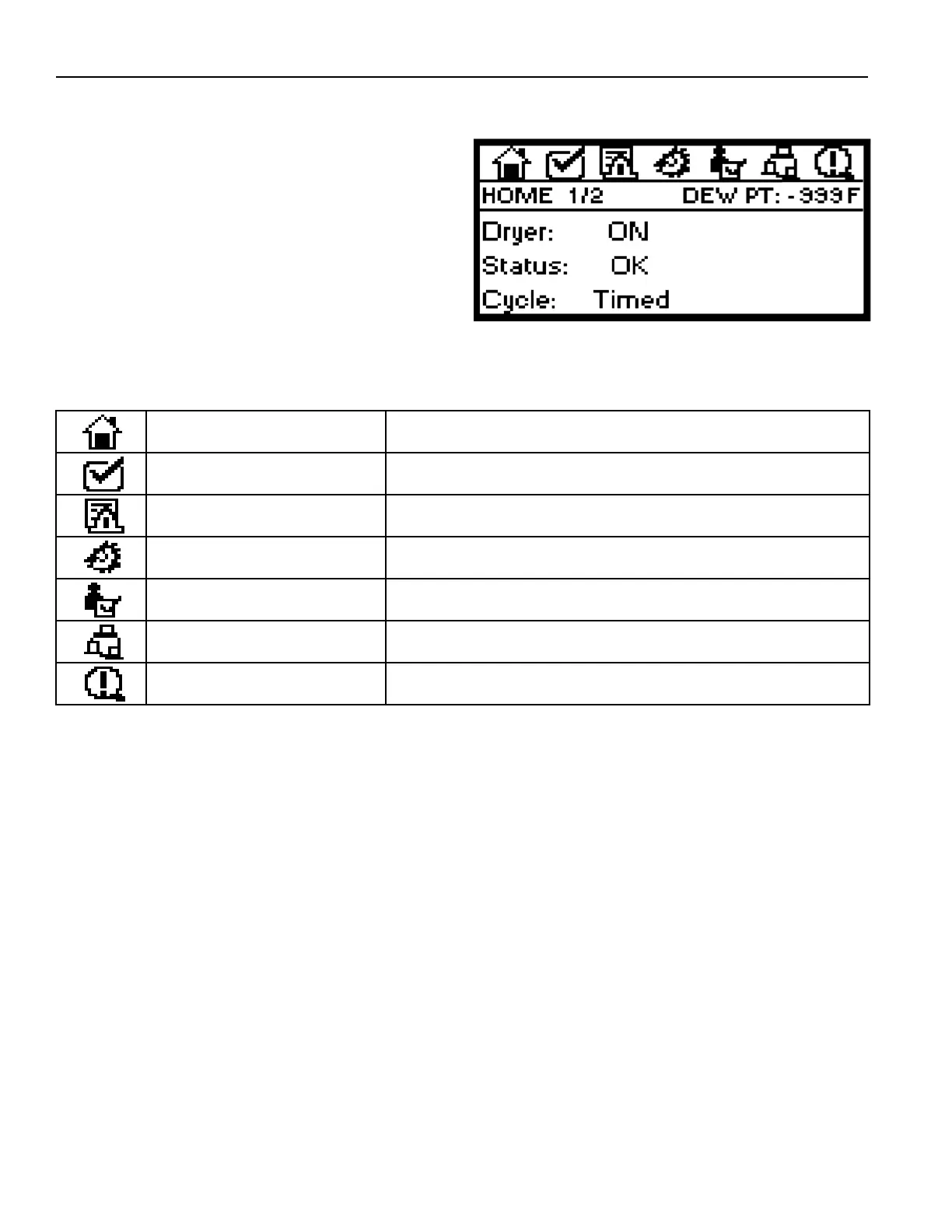
6.9.2 DIGITAL DRYER CONTROLLER DISPLAY
PARAMETERS
The controller display is a graphical interface that allows user
access to information and settings through use of UP/DOWN/
RIGHT/LEFT Navigation Keys. Information is organized under
Menu Icons as listed in the Table below.
Menu Icons are visible at the top of the display screen. Press the
RIGHT or LEFT Navigation Keys to scroll through the Icons. The
selected Icon will be highlighted (darken) when active.
Multiple SCREENS can be viewed within each Icon. Use the UP
and DOWN Navigation Keys to navigate within each Icon. The
second row of the display indicates which SCREEN is visible.
NOTE: Following any period of inactivity, the display will
revert to the HOME SCREEN as shown above.
PARAMETER CHANGE INSTRUCTIONS
To Make Numeric Value Changes:
1. Use UP/DOWN Navigation Keys to highlight the value that
needs to be changed.
2. Press ENTER Button and enter a revised value using
numeric entry keys.
3. Press ENTER Button again to save the new value. The
Dryer Operating Program will then use the new value.
Text Value Changes or TEST Button Changes:
1. Use UP/DOWN Navigation Keys to highlight the value that
needs to be changed.
2. Press the +/- button to change the value to the new setting.
ZPB Controller Display
Display of dryer status, program sequence information, alarm status and
drain test information.
Location to adjust/change dryer operation settings. Password is required
to access.
View historical information related to alarms, power up condition.
General reminders to replace fi lter elements, inspect drains, and others.
Time & Date; Language (English is default); Backup solenoid drain
adjustment; MLC adjustment (optional)
Establish remote communication settings.
DISPLAY PARAMETER
HOME
TECHNICIAN MODE
ALARM INDICATION/EVENT LOG
MAINTENANCE ALERTS
GENERAL SETTINGS
Displays information related to sensors, valve activation, drain status, etc.
COMMUNICATIONS
STATUS
DESCRIPTIONMENU ICON
6.9.2.1 TOWER STATUS INDICATION LEGEND
LT: Left Tower
RT: Right Tower
DRY: Tower is pressurized and drying the compressed air
REGEN: Tower is depressurized and the desiccant bed
is being regenerated
VLV CHG: Valve change sequence in process to direct
compressed air and purge air through proper fl ow
paths
REG*: Tower is pressurized without fl ow. This occurs when
the tower that’s designated for regeneration is not
required to be depressurized when either, 1) MLC
set-point is satisfi ed and purge air is not required, or
2) PurgeSync™ function is activated and the reduced
purge time cycle is completed.