INTRODUCTION
11
EN 3201.758.001a 2016-02
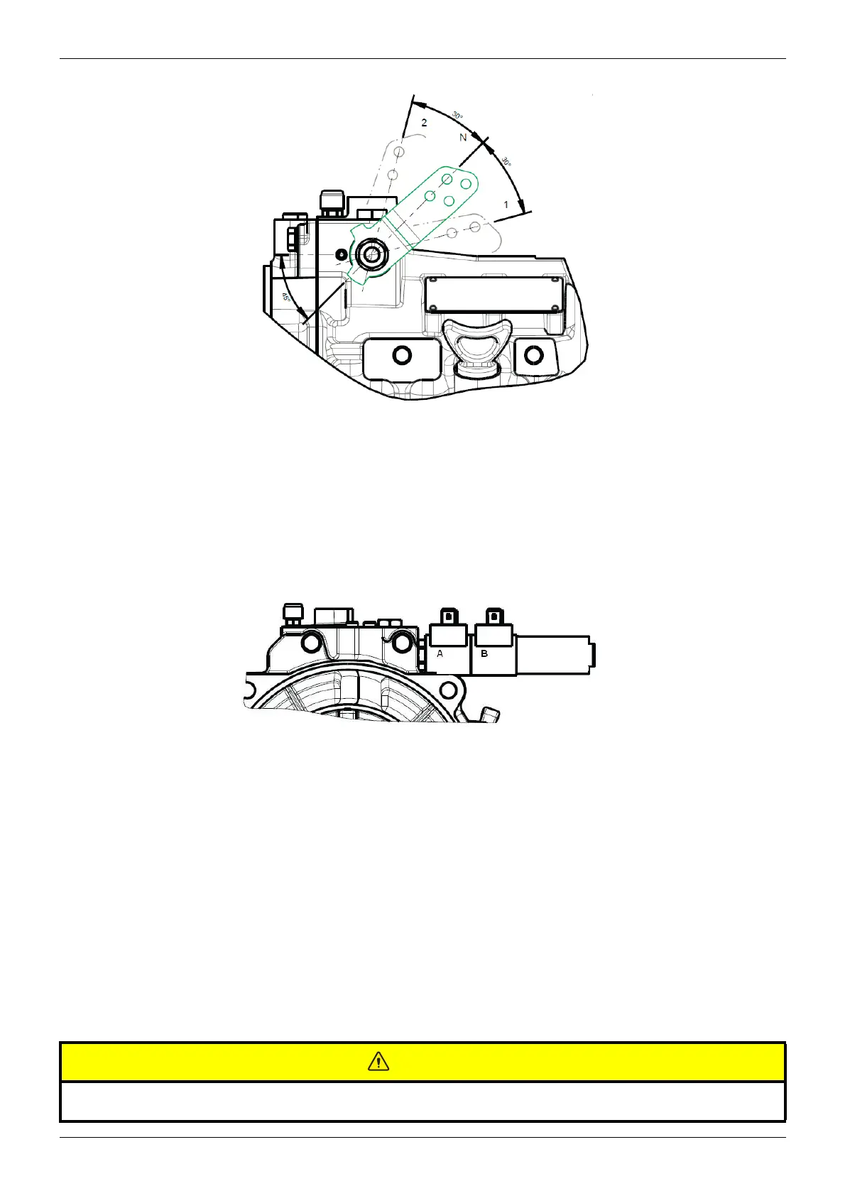
• Pos. 1: Output shaft rotation opposite to engine rotation
• Pos. N: Neutral
• Pos. 2: Output shaft rotation same as engine rotation
1.3.4 ELECTRIC CONTROL VALVE
The solenoid that corresponds to Pos. 1 of the control lever of the mechanical control valve, is the solenoid "A": the
energization of said solenoid rotates the output shaft in C.E.R. (Rotation opposite to direction of rotation of engine)
The transmission ratio, for both the engine and counterengine rotation modes, is stated on the identification plate. The
three types of operation are controlled by the control valve (mechanical or electrical).
The casing of the Main Unit also acts as a sump separated from the "V drive Unit" A magnet, placed under the sepa-
ration plate, removes steel particles from the oil, preventing damage to the hydraulic circuits.
Oil through the pump suction go to the control unit valve, where there is pressure regulation valve that reduces the
delivery pressure of the pump to the necessary clutch operating pressure.
MAIN UNIT OIL SUMP MUST BE COOLED BY THE COOLING SYSTEM OF THE BOAT USING THE HOLES 3/8 "(INLET
AND OUTLET) PROVIDED ON THE HOUSING.
In Unit V drive Unit there is an integrated heat exchanger for cooling oil inside casing V drive unit
THE HEAT EXCHANGER MUST ALWAYS BE CONNECTED TO THE COOLING WATER WITH THE PUMP RUNNING
BEFORE ENGAGE THE CLUTCH.
Before operating the gearbox, check oil leves (both Main Unit and V-drive Unit)
See Technical data (p. 17).



 To Next Page