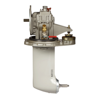
The ZF SD-10 Sail Drive is a robust and reliable transmission unit designed for marine applications, specifically for sailboats. This manual provides comprehensive instructions for its operation, maintenance, and corrosion protection, ensuring safe and enjoyable use.
Function Description
The ZF SD-10 Sail Drive acts as a transmission unit, connecting the engine to the propeller. Its primary function is to transmit power from the engine to the propeller, enabling the boat to move through water. It also allows for shifting between neutral, forward, and reverse positions, controlling the propeller's rotation and direction. The unit is designed to be sturdy and reliable, ensuring efficient power transfer and maneuverability for the vessel.
Usage Features
The SD-10 Sail Drive is designed for straightforward operation, though adherence to specific procedures is crucial for its longevity and performance.
- Shifting Gears: During normal operation, the transmission should only be shifted with the engine at idle speed. In emergency situations, shifting at higher speeds is permissible.
- Neutral Position: When the engine is off and the boat is sailing, being towed, or anchored, the propeller may turn with the water current. In such cases, placing the gearbox in the neutral position allows the propeller to rotate freely.
- Locking the Propeller: Alternatively, to lock the propeller when sailing with the engine off, the gearbox can be shifted to the opposite position of the travel direction. It is explicitly warned not to put the shifting lever in the forward position, as this could damage the transmission.
- Engine Idling without Propeller Drive: If the engine is running idle but the propeller shaft should not be driven (e.g., when charging the battery with a generator), the shifting lever must be held in the neutral position (N) to prevent the boat from moving.
- Gear Shift Operation: The control rod or cable for gear shifting must be easily movable. The minimum travel for the gear shift lever is specified as 35 mm (1.3/8") for the outer pivot point and 30 mm (1.3/16") for the inner pivot point. In the neutral position, the lever should be perpendicular to the control rod or cable. The gear shift lever can be fixed in any position using a clamping screw, maintaining a minimum distance of 0.5 mm (0.02") between the lever and the cover. Any opening or loosening of the cover requires renewed adjustment by specialized personnel. Regular checks of these specifications are required.
Maintenance Features
Proper maintenance is critical for the SD-10 Sail Drive's reliability and to ensure warranty validity. The manual outlines a detailed maintenance schedule, emphasizing that these procedures are for the transmission unit, not the engine.
- Routine Maintenance (Daily/Refueling):
- Check the transmission oil (fluid) level.
- Check battery connections and acid level.
- Routine Maintenance (Every Two Months of Operation):
- Check the antifouling condition and apply it to the foot if necessary.
- Ensure clamps and wiring connections are secure.
- Clean the clamps every two operating months or every 50 hours, whichever comes first. In saltwater use, this interval is reduced to every 25 hours or 30 days.
- Scheduled Maintenance (After First 25-30 Hours):
- Scheduled Maintenance (Every 250 Hours or Once a Year):
- Change the oil.
- Lubricate and check that the sea chest opens and closes freely.
- Lubricate the propeller shaft splines and tighten the propeller nuts.
- Check that pipe fittings are properly tight.
- Check the grounding circuit for loose or damaged connections.
- Ensure electrical system fasteners are not loose, damaged, or corroded, and check for loose, damaged, or corroded wires and connectors.
- Check that hose clamps on flexible pipes are properly tight.
- Apply antifouling.
- Scheduled Maintenance (Each Year):
- Check the foot sealing membrane for cracks or water seepage.
- Scheduled Maintenance (Every 7 Years):
- Replace the foot sealing membrane.
Oil Level Check and Change:
- Checking Oil Level: Remove the dipstick, wipe it clean, insert it so it rests on top of the threads, remove it again, and check that the fluid level is between the minimum and maximum marks. Add oil as necessary. The maximum (a) and minimum (b) marks are indicated on the dipstick, with (c) being the upper edge of the threaded hole and (d) the rod.
- Oil Change Procedure:
- Unscrew the oil dipstick.
- Prepare a container to collect the fluid.
- Remove the lower plug and drain the oil. Dispose of used oil properly.
- Connect a hand oil pump to the oil drain hole, being careful not to damage the thread.
- Using a low-pressure pump, add 3 liters of SAE 15W-40 oil.
- Replace the O-rings on the oil cap, lubricate them, and reassemble.
- Remove the oil pump fitting and quickly install the oil plug, torquing it to 10 Nm.
- Add oil at the dipstick hole until the proper level is reached as indicated on the dipstick.
- Screw in the oil dipstick.
Propeller Removal and Installation:
- Removing Propeller:
- Place a block of wood between a propeller blade and the hull.
- Using a 6mm Allen wrench, loosen and remove the locking screw of the bullet.
- Insert a suitable tool into the hole, loosen, and remove the propeller spinner nut.
- Remove the wooden block.
- Remove the propeller. If necessary, use a plastic hammer and gently tap to remove it.
- Remove the propeller sleeve.
- Installing Propeller:
- Assemble the propeller shaft thrust bearing sleeve, installing the chamfered side away from the propeller.
- Apply anti-corrosion grease (antifouling grease, special lubricant, or marine lubricant with Teflon) to the grooves of the propeller shaft.
- Align the splines and insert the propeller onto the propeller shaft, ensuring it fits evenly.
- Wipe off excess grease.
- Install the propeller shaft nut.
- Place a block of wood between one of the propeller blades and the hull.
- Mount the special insert T2 on a suitable torque wrench, insert it into the hole in the propeller nut, and tighten to a torque of 125 Nm.
- Install the locking screw in the center.
- Tighten the locking screw to a torque of 23 Nm.
Corrosion Protection:
The SD-10 is equipped with a replaceable sacrificial anode on the lower leg of the drive, designed to dissolve in response to electrical current in seawater. This anode is not designed to accommodate other hardware or excessive electrical currents from additional components or changes to the vessel's AC and DC systems.
- Galvanic Protection System: The design of the engine's electrical system impacts the selection of a proper galvanic protection system.
- Isolated Systems: If the engine alternator and starting motor use an isolated circuit (with both battery + and – connection terminals), the system is considered "isolated."
- Non-Isolated Systems: If either the starter motor or alternator uses a single battery + and grounds through the engine body or case, the SD-10 and engine system are considered "grounded" to the battery negative and not isolated.
- Suggested Actions: Review ABYC guidebook, Section E-2, for information on this topic. A review of the electrical bonding system by an expert is recommended upon vessel delivery to ensure appropriate sacrificial anodes are installed to protect mechanical components from galvanic corrosion. Changes to the vessel's AC and DC systems can impact the protection of the installed anode system. ZF Marine is not responsible for damage to the SD-10 resulting from failure to maintain a balanced galvanic protection system.
- Anode Replacement:
- Remove the propeller.
- Using a 6mm Allen key, remove the screws of the anode.
- Remove the anode from the foot. If necessary, use a plastic mallet.
- Remove the spacer sleeve and clean any scale.
- Apply a thick layer of lubricant and/or corrosion protection material to the propeller shaft splines. Insert the propeller thrust sleeve onto the shaft.
- Place a new anode on the foot.
- Tighten to a torque of 12 Nm using the cross method.
- Install the propeller.
This comprehensive approach to operation and maintenance ensures the ZF SD-10 Sail Drive remains a reliable component of the vessel's propulsion system.