5. Wiring for the room temperature sensor
A temperature sensor that can be fitted to a wall mea-
sures the room temperature in order to automatically
regulate the heating. The standard sensor wire is
approximately 2.5 m long.
The sensor may not be placed in a draught,
direct sunlight or the warm air flowing out
of the heater. This may cause incorrect
temperature indications.
6. Unpacking
Save all packaging materials for possible future trans-
portation.
A) Remove the cardboard (drilling) template and the
user’s manual from the packaging.
B) Remove the base plate and the box with the
installation kit from the packaging.
C) Remove the heater from the packaging.
D) Remove the plastic bag covering the heater.
E) Remove the plastic bag containing the parts.
F) Remove the exhaust pipe from the bottom of the
box.
G) Check that all parts are present.
Only the standard feed and exhaust system
is supplied with the heater.
Chapter 1, INSTALLATION
29
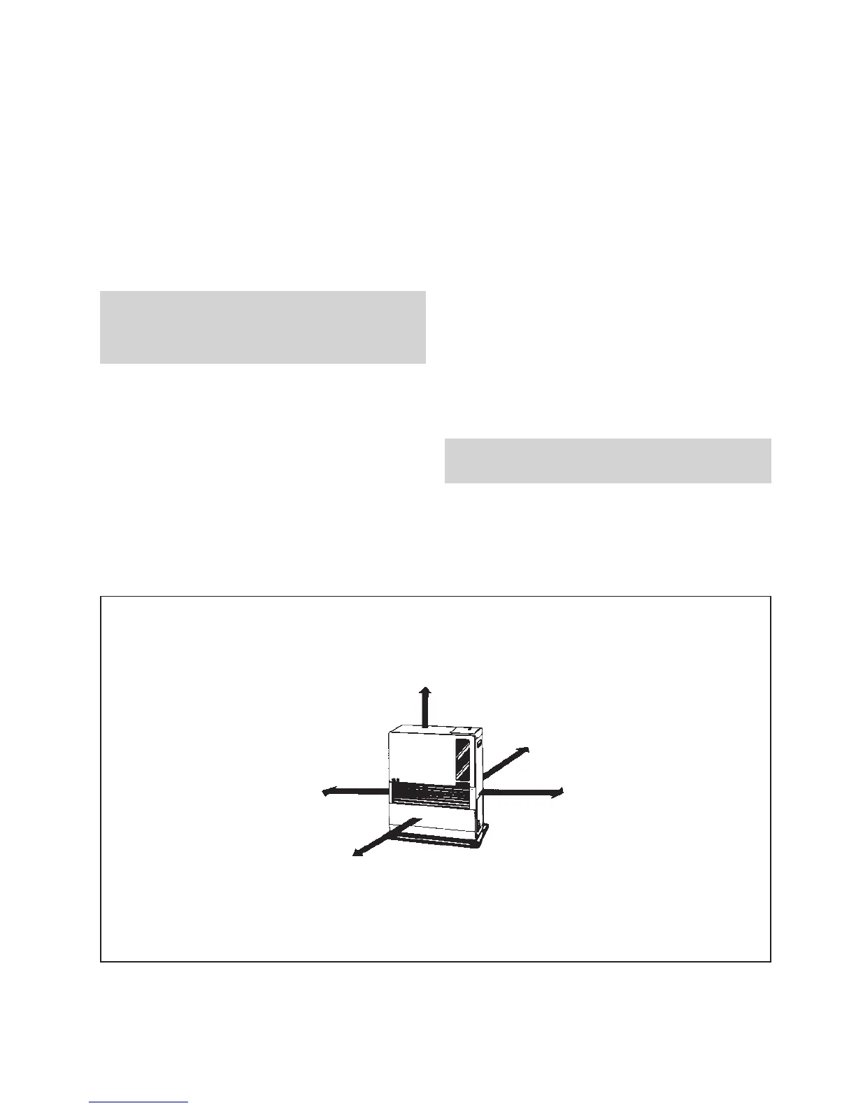
Fig. 1-1: Gaps heater/exhaust pipe
Laser 95
More than 60 cm
More than 30 cm
More than 1,5 m
More than 30 cm
More than 10 cm
☞
☞



 To Next Page