-76-
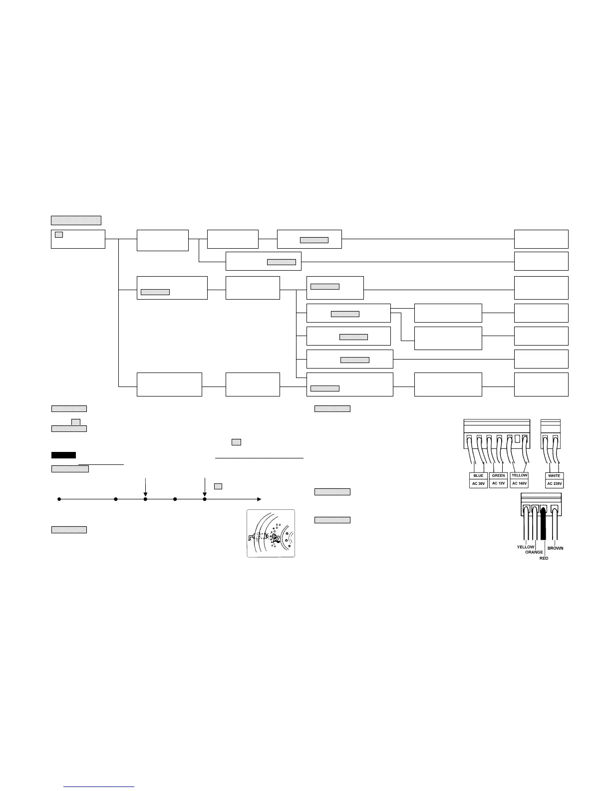
E-2 DISPLAY
Yes
No
Explanation 1
If pressing the Power Button immediately after burning extinguishes, the Flame Detector is actuated to
display “
E-2”, by which no ignition can be made.
Explanation 2
The REPEAT mechanism is provided to correct a miss ignition. If ignition cannot be made, the operation
will automatically go over again. If this second ignition cannot be made, “
E-2” will be displayed to stop
operation.
CAUTION The expression of “no ignition” above implies that the Primary Flame Rod current is
lower than 0.3 µA.
Repeat Timing
“E-2” is displayed and
Preheating Ignition Preheating Ignition Burning extinguished.
40-150 sec. (SRE 156, 166, 176)
50-210 sec. (SRE 250)
40 sec. 40 sec. 40 sec.
60-180 sec. (SRE 260)
The preheating time varies according to the temperature of Burner Thermistor.
The Operation lamp flashes during the preheating time.
Explanation 3
No operation can be made if only the Flame Rod is stained with carbon. If,
however, the Primary Flame Rod and the Burner wall, or the Burner Ring are
connected with carbon, the Flame Detector is actuated. The easier tendency of
carbon adhesion (as shown in the right figure) is caused by the Burner Ring
which is out of position, or by nonconforming air flow rate.
Explanation 4
The malfunction due to the broken wire of the Transformer
is to be checked by Tester as follows:
(1) Disconnect the Transformer.
(2) Apply the test pin of the Tester to the terminal of each
lead wire as shown in the following figure, to check to
see if the lead wire and related terminal are
electrically conductive.
(3) The connection of the lead wire and terminal must be
defective, if the above check shows non- or unstable
conductance.
(4) If there is any electrical conductance found between
each of any of the two of the blue, green, yellow and
white lead wires, their connection must be wrong.
Explanation 5
Measure the output of the output terminal for Fuel Pump. DC 24V is outputted
between the yellow and the orange lead wires after preheating has been
completed.
Explanation 6
If a silicon compound split hair coating liquid or a hair treatment solution is used in
the room while being heated by kerosene fan heater, the Primary Flame Rod and
the Burner Ring are deposited with white products on the surface of the Flame
Rods, which makes it unable to detect the flame current and thereby causing a
miss ignition, or to cease the combustion. If this occurs, remove the white products
from the Primary Flame Rod and the Burner Ring with the use of sand paper. Give
this cleaning work by leaving the Primary Flame Rod being mounted to the Burner.
E-2 is displayed and
burning extinguishes.
Displayed at the



 To Next Page