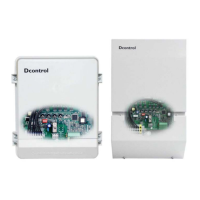
Operating instructions Dcontrol Date 0730
TBL02_54-GB 0730 Part-No. 00153238-GB
Page 2 / 28
Contents
1. General.................................................................................................................................. 4
2. Safety measures................................................................................................................... 4
3. General description ............................................................................................................. 5
3.1 Scope of applications ........................................................................................................................................... 5
3.2 Technical data ...................................................................................................................................................... 5
3.3 Versions ............................................................................................................................................................... 6
3.4 Power decrease for increased ambient temperatures ......................................................................................... 7
4. Installation ............................................................................................................................ 8
4.1 Mounting............................................................................................................................................................... 8
4.2 Minimum space requirement................................................................................................................................ 8
4.3 Outdoor installation .............................................................................................................................................. 8
4.4 Installation location for agriculture........................................................................................................................ 8
4.5 Temperature influences during commissioning ................................................................................................... 8
4.6 Residual-current-operated protective device ....................................................................................................... 8
4.7 Potential at control voltage connections .............................................................................................................. 8
4.8 Employment in the IT Net..................................................................................................................................... 8
5. Electrical connections ......................................................................................................... 9
5.1 Mains connection ................................................................................................................................................. 9
5.2 Adjustment to specific mains conditions .............................................................................................................. 9
5.3 Motor connection.................................................................................................................................................. 9
5.3.1 Motor feeder cable ......................................................................................................................................................9
5.4 Motor noise......................................................................................................................................................... 10
5.5 Motor protection ................................................................................................................................................. 10
5.6 Special function only for PKDM..: Motorstart with maximum output voltage „Hard start function “ ................... 10
5.7 Signal cable (sensor cable)................................................................................................................................ 10
5.8 Enable ON / OFF................................................................................................................................................ 11
5.9 Signal connection or sensor connection (Analog IN1, Analog IN2)................................................................... 11
5.10 External speed setting (operation as a speed controller) ................................................................................ 11
5.10.1 Inverting setting signal...........................................................................................................................................11
5.10.2 Operation with second setting signal at input „E2“ (special function only for PKDM..)..................................11
5.11 Sensor Connection (operation as a P-controller)............................................................................................. 12
5.11.1 Operation with a second sensor signal at input “E2” for dual circuit condensers (only for PKDM..) ............12
5.12 Switch over control function at Digital IN 2 (only for operation as P-controller)............................................... 12
5.13 Fault indications ............................................................................................................................................... 12
5.14 Voltage supply for external equipment............................................................................................................. 12
5.15 Output voltage (0-) 10 V (needed only as required) ........................................................................................ 12
6. General settings and operating elements........................................................................ 13
6.1 Programming the operating mode (speed controller / P- controller).................................................................. 13
6.2 Controls .............................................................................................................................................................. 14
7. Settings for operation........................................................................................................ 15
7.1 Settings for operation as a speed controller ...................................................................................................... 15
7.1.1 Setting of output voltage via potentiometer „SET“ ...............................................................................................15
7.1.2 Setting of output voltage via external signal or external potentiometer..............................................................15
7.1.3 Min. speed „n-min“ (minimum output voltage or basic speed) ............................................................................15
7.1.4 Max. speed „n-max“ (derating) and Cos φ-adjustment ......................................................................................... 15
 Loading...